
Internal circulation dynamic membrane bioreactor

A bioreactor and dynamic membrane technology, applied in the direction of sustainable biological treatment, aerobic process treatment, etc., can solve the problems of poor removal of pollutants, uneven mixing of activated sludge, and small cross-flow velocity of mixed liquid, etc., to achieve The effects of delaying membrane fouling, prolonging the backwash cycle, and increasing the cross-flow velocity

Inactive Publication Date: 2006-12-06
SHANDONG UNIV
View PDF0 Cites 10 Cited by
  • Summary
  • Abstract
  • Description
  • Claims
  • Application Information

AI Technical Summary

Problems solved by technology

When the dynamic membrane bioreactor with the above structure is in operation, the dead zone rate of the reactor is large, the activated sludge is mixed unevenly, and the removal effect on pollutants is poor; Small, insufficient flushing of the dynamic membrane, easy to cause membrane fouling

Method used


Image

  • Internal circulation dynamic membrane bioreactor

Examples


Embodiment 1

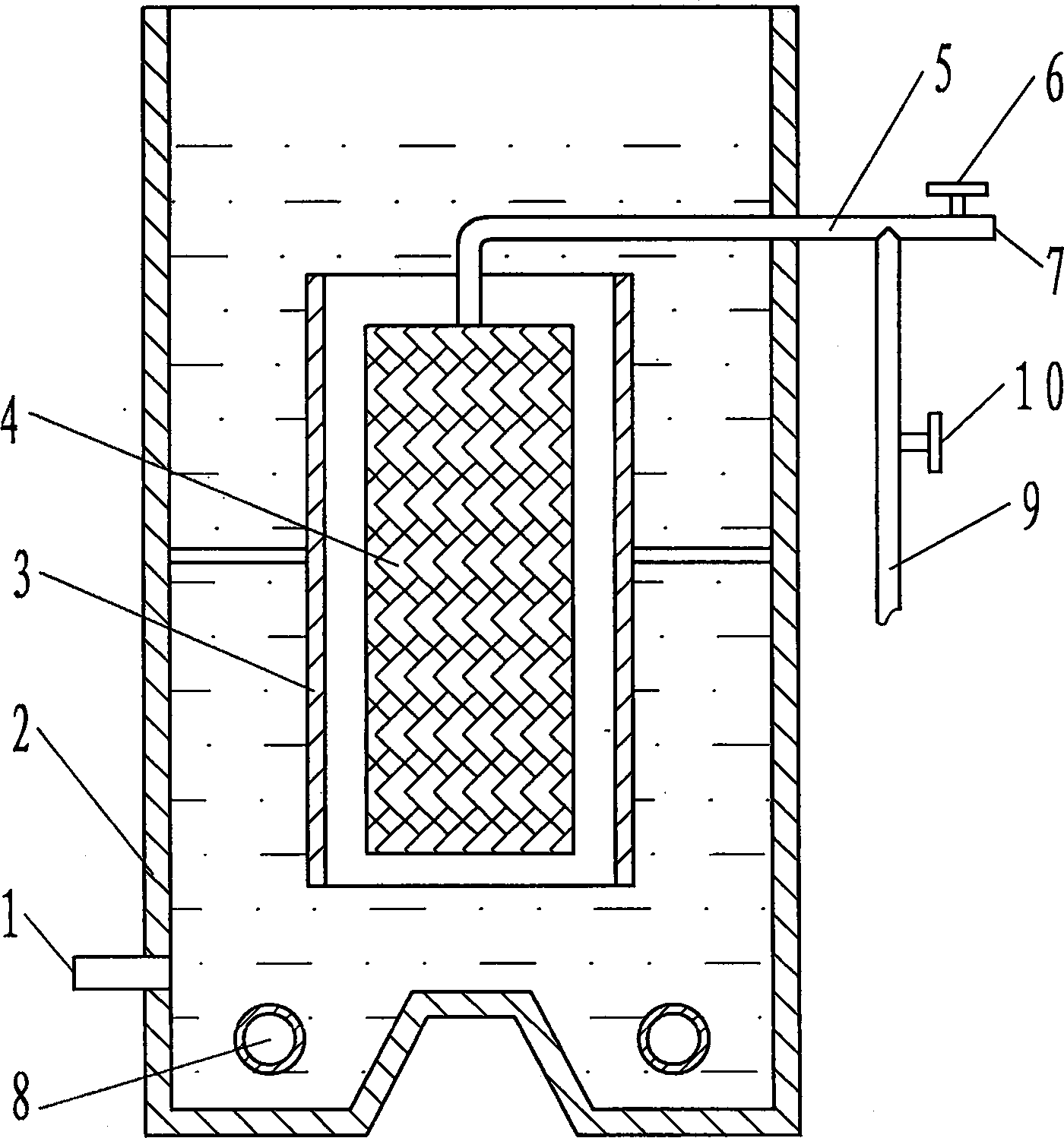
[0012] As shown in the drawings, the internal circulation dynamic membrane bioreactor of the present invention includes an outer cylinder 2 , an inner cylinder 3 , a membrane module 4 , an aeration pipe 8 and a backwash aeration pipe 9 . The lower end of the outer cylinder body 2 is sealed, the upper end is open, and the lower part is provided with a water inlet 1 . The upper and lower ends of the inner cylinder body 3 are all open, and are contained in the outer cylinder body 2, and the distance between the bottom end and the inner bottom surface of the outer cylinder body 2 is 1 / 10 of the total height of the outer cylinder body. Membrane module 4 is made of sieve silk, set in the inner cylinder 3, its upper end is provided with a water outlet pipe 5 protruding from the outer cylinder, the end of the water outlet pipe 5 is a water outlet 7, and the front of the water outlet 7 is provided with a valve 6 . A backwash aeration pipe 9 is also connected to the water outlet pipe 5...

Embodiment 2

[0016] The structure of the internal circulation dynamic membrane bioreactor is the same as in Example 1. The MLSS of the reactor is 8000mg / L, the DO is 2.0-4.0mg / L, the COD of the influent is 500mg / L, and the ammonia nitrogen in the influent is 80mg / L. During operation, when the gas-water ratio is 40:1, the effluent COD is 28mg / L, the effluent ammonia nitrogen is 1.5mg / L, and the turbidity of the effluent is 4NTU. The backwash cycle of the reactor can be stabilized at 90h.

Embodiment 3

[0018] The structure of the internal circulation dynamic membrane bioreactor is the same as in Example 1. The MLSS of the reactor is 8000mg / L, the DO is 2.0-4.0mg / L, the COD of the influent is 150mg / L, and the ammonia nitrogen in the influent is 50mg / L. During operation, when the gas-water ratio is 40:1, the effluent COD is 22mg / L, the effluent ammonia nitrogen is 1.0mg / L, and the turbidity of the effluent is 4NTU. The backwash cycle of the reactor can be stabilized at 90h.


PUM


Abstract

This invention provides an internal cycle dynamic membrane bioreactor. The bioreactor comprises an outer cylinder, an inner cylinder, a membrane component, an aeration pipe and a back-washing aeration pipe. The lower end of the outer cylinder is sealed while the upper end is open, and an water inlet is set at the lower end. The inner cylinder is set in the outer cylinder, and both ends of the inner cylinder are open. The membrane component is set in the inner cylinder, and a water outlet pipe is set at its upper end and extends out of the outer cylinder. The water outlet pipe is connected with the back-washing aeration pipe, which is set between the outer and the inner cylinders. The bioreactor has such advantages as reduced dead zones, improved uniformity of sludge mixing, increased cross flow speed of the mixed liquids in the inner cylinder, retarded membrane pollution, prolonged back-washing cycle, and improved operation stability.

Description

technical field [0001] The invention relates to a dynamic membrane bioreactor and belongs to the technical field of membrane bioreactors. Background technique [0002] The currently used dynamic membrane bioreactors all adopt the form of lateral aeration, that is, a baffle is installed in the reactor, and the baffle divides the reactor into two parts, the left and the right, and the two parts are connected up and down. A membrane module is installed at one end, water is fed into the other end, aeration is made at the water inlet end, and water is discharged by using the water pressure difference between the liquid level of the reactor and the water outlet of the membrane module. When the dynamic membrane bioreactor with the above structure is in operation, the dead zone rate of the reactor is large, the activated sludge is mixed unevenly, and the removal effect on pollutants is poor; Small, the flushing of the dynamic membrane is not enough, and it is easy to cause membrane...

Claims


Application Information

Patent Timeline
IPC IPC(8): C02F3/02
CPCY02W10/10
Inventor 张建邱宪锋张成禄高宝玉
Owner SHANDONG UNIV
Learn More