
Method for testing real stress of self-compensating concrete structure and concrete real stress gauge

A technology of concrete structure and true stress, applied in the direction of material inspection products, etc., can solve the problem that concrete stress cannot be accurately tested.

Inactive Publication Date: 2006-11-22
郑万山 +2
View PDF0 Cites 8 Cited by
  • Summary
  • Abstract
  • Description
  • Claims
  • Application Information

AI Technical Summary

Problems solved by technology

[0004] One of the purposes of the present invention is to provide a self-compensating concrete structure true stress testing method, which can really solve the difficult problem of concrete real stress testing, by using the isolation device to compensate the inelastic strain by using the characteristics of the concrete itself, and reducing the non-elastic strain to the greatest extent. The impact of elastic strain on the test results can directly measure the stress of the concrete structure, without the need to calculate the stress from the strain, so as to overcome the problem that the concrete stress cannot be accurately measured in the current engineering field

Method used


Image

  • Method for testing real stress of self-compensating concrete structure and concrete real stress gauge
  • Method for testing real stress of self-compensating concrete structure and concrete real stress gauge
  • Method for testing real stress of self-compensating concrete structure and concrete real stress gauge

Examples


Embodiment 1

[0061] Embodiment 1 Self-compensating concrete structure true stress test method, the method comprises:

[0062] 1) According to the test requirements, determine the accuracy and range of the force sensor, and select a static or dynamic force sensor with good stability;

[0063] 2) Make or install a suitable isolation device, the length of the isolation device should not be less than 10 times the thickness of the force sensor;

[0064] 3) Fix the force sensor inside or at the end of the isolation device to form a concrete real stress gauge, and record the cross-sectional area inside the isolation device;

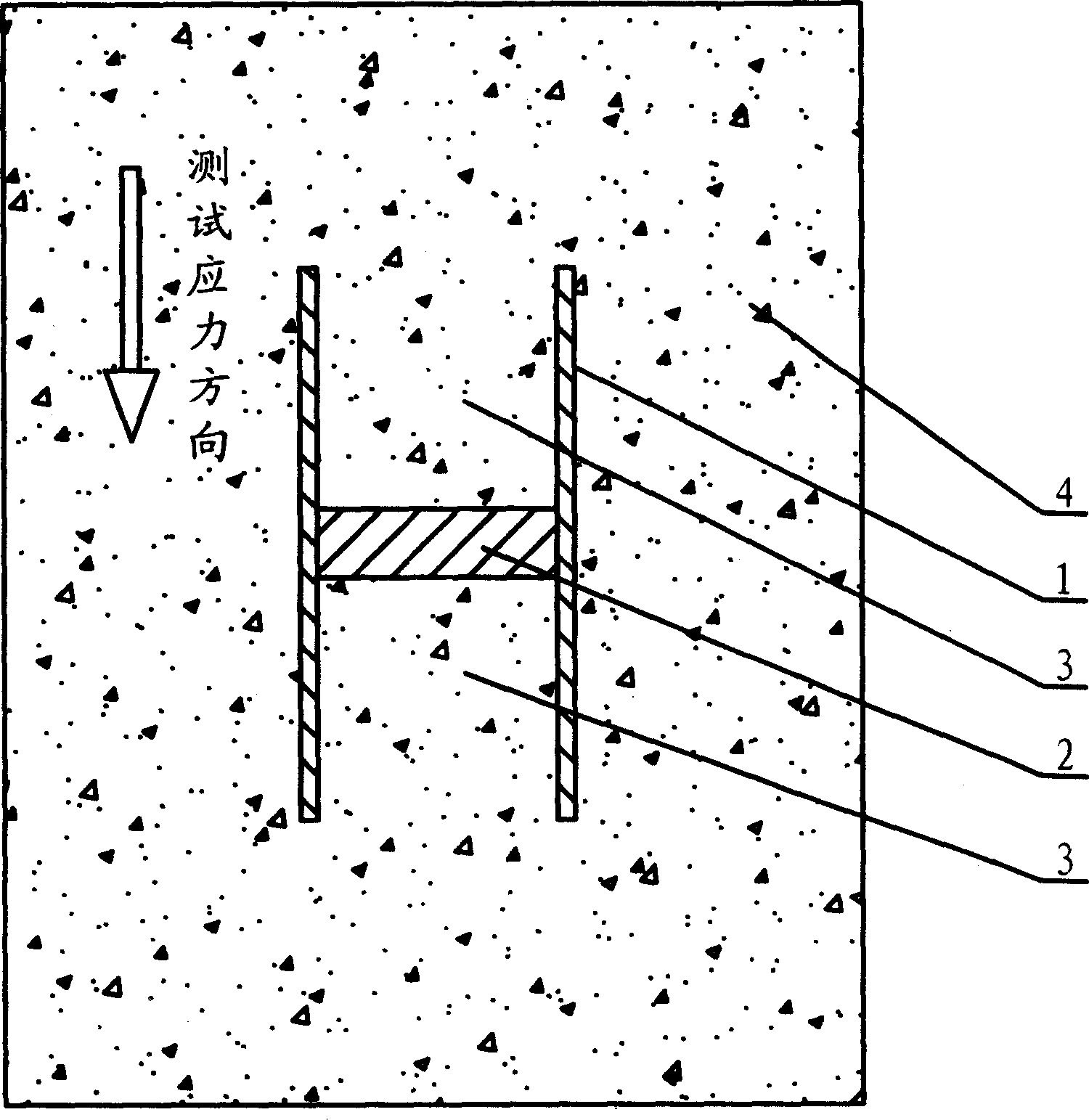
[0065] 4) Before concrete pouring, place a real concrete stress gauge along the test direction at the part where the stress needs to be tested, and lead the data line or power line out of the formwork;

[0066] 5) Pouring concrete and vibrating it near the real stress gauge of the concrete to ensure that the concrete inside and outside the isolation device is evenly dense; ...

Embodiment 2

[0068] Embodiment 2 Concrete True Stress Meter

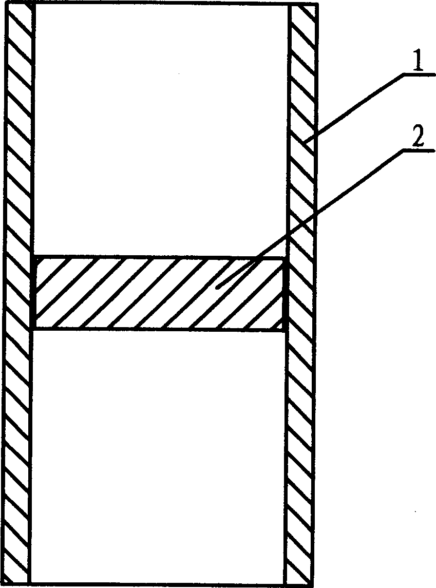
[0069] see figure 1 , figure 1 It is a structural schematic diagram of an embodiment of the concrete real stress gauge of the present invention. It can be seen from the figure that the concrete real stress gauge made by the present invention includes an isolation device 1 and a force sensor 2, and has a simple structure and is convenient for application. Place the force sensor 2 inside the isolation device 1 and fix it. The force sensor is a pie-shaped structure whose cross section matches the cross section of the isolation device. When the force sensor is located at a certain part in the middle of the isolation device, the concrete in the isolation device is divided into two parts by the force sensor; when the force sensor is located at the end of the isolation device, the internal concrete is a whole.

[0070] The force sensor of the present invention can directly use commercially available vibrating wire pressure cells, pie...


PUM


Abstract

The related test method for true stress of concrete structure comprises: setting a equal-section insulator on test direction to isolate the concrete in and out of the device, using a force senor to test concrete column axial force in device to obtain the objective value. This invention eliminates non-spring strain effect, has reliable result and well practice.

Description

technical field [0001] The invention relates to a concrete structure stress testing method, in particular to a self-compensating concrete structure real stress testing method, and also relates to a concrete real stress gauge adopted in the method. Background technique [0002] Concrete structure is the most common building structure in civil engineering. People make full use of its high compressive strength and good durability to build a large number of artificial buildings. Since the invention of concrete materials, it has been greatly promoted. With the development of science and technology, the characteristics of concrete materials are gradually recognized by engineers: concrete is not an ideal linear elastic material, and it will shrink after pouring; under load, it not only produces elastic strain, but also produces Creep; expansion or contraction under the influence of temperature. Due to the huge difference in material properties between the sensor and concrete, when...

Claims


Application Information

Patent Timeline
Patent Type & Authority Applications(China)
IPC IPC(8): G01N33/38
Inventor 郑万山郑罡张又进
Owner 郑万山
Learn More