Output power compensating method and switching controller

A technology for output power and control devices, which is applied in the direction of control/regulation systems, conversion equipment with intermediate conversion to AC, instruments, etc., and can solve problems such as aggravation of output power differences

Inactive Publication Date: 2010-04-28
SYST GEN
View PDF4 Cites 0 Cited by
  • Summary
  • Abstract
  • Description
  • Claims
  • Application Information

AI Technical Summary

Problems solved by technology

[0016] Comparing the above equations (3) and (4), since the PWM controller U 1 Internal transmission delay time t d Will make the excitation current more than the theoretical value (V IN / L P )×t d , so there will be a larger power limit voltage at high input voltage than at low input voltage
Although the transmission delay time t d Very short, usually in the range of 200ns to 350ns, and at higher switching frequencies, the transmission delay time t d The output power difference caused by high and low input voltage will be more severe

Method used


Image

  • Output power compensating method and switching controller
  • Output power compensating method and switching controller
  • Output power compensating method and switching controller

Examples


Embodiment Construction

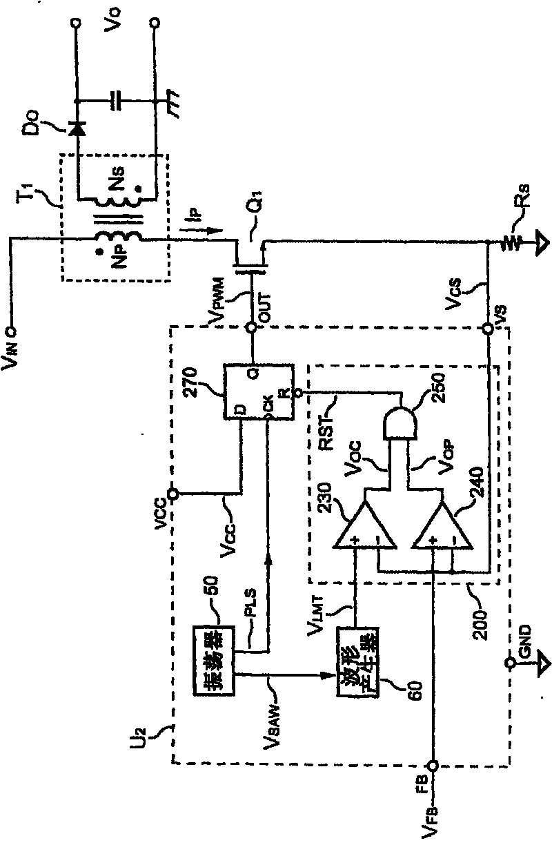
[0045] Please refer to image 3 , is a schematic circuit diagram of the present invention used in the power supply. The present invention has a switching control device for output power compensation, which is used in a power supply. The power supply uses the switching control device of the present invention to control the power switch Q 1 for transformer T 1 switch. At the same time, a sense resistor R S with power switch Q 1 connected in series to obtain flow through the power switch Q 1 The primary side switching current I P , and generate a current detection signal V CS . The switching control device of the present invention detects resistance R S Get the current detection signal V CS , and then control the power switch Q after operation 1 switching action.

[0046] The present invention utilizes an oscillator 50 to connect a waveform generator 60, and the oscillator 50 outputs a sawtooth wave signal V SAW and a pulse signal PLS, and transmit the sawtooth signal...


PUM


Abstract

The invention discloses the method of output power compensation of the power supply server and the switch controller, the one wave generator is used to connect the oscillator, the sawtooth wave signalis receipted to output the period three segment limiting signal; the period three segment limiting signal is send to the comparing unit. The comparing unit receives the one current measuring signal and the said period limiting signal, then it can be used to output one resetting signal; the one synchronous signal output unit connects to the said the comparing unit, the oscillator and the one powerswitch, the reset signal and the one pulse signal is recepted, the pulse signal is in-phase to output the one driving signal to the power switch, so the output power compensation of the power supplie r during the high, the low output voltage can be realized.

Description

technical field [0001] The present invention relates to a method of output power compensation and a switchable control device, especially to a power supply that uses the output periodic three-segment limit signal to compare with the obtained current detection signal, as a power supply A method for output power compensation under high and low input voltages and a switching control device thereof. Background technique [0002] Pulse Width Modulation (PWM) is a known technique for controlling and stabilizing the output power of a power supply. Power supplies must provide various protection functions, such as over-voltage, over-current and over-power protection. Overcurrent and overpower protection are used to protect the power supply and peripheral circuits to avoid permanent damage. In the over-power protection, the function of output power compensation is designed as the power supply has the same overload protection point under high and low input voltage. [0003] Please r...

Claims


Application Information

Patent Timeline
Patent Type & Authority Patents(China)
IPC IPC(8): H02M3/28G05F1/66
Inventor 杨大勇
Owner SYST GEN
Why Eureka
Try Eureka