Vertical axis and moving blades combined windmill

A technology with movable blades and vertical shafts, which is applied to wind turbines, motors, wind turbines, etc. at right angles to the wind direction. It can solve the problems of manufacturing large windmills, overloading of generators, unreasonable structures, etc., and achieves low cost and enhanced High stability and wind energy conversion efficiency

Pending Publication Date: 2019-07-05
石峰
View PDF0 Cites 0 Cited by
  • Summary
  • Abstract
  • Description
  • Claims
  • Application Information

AI Technical Summary

Problems solved by technology

[0007] For this reason, the embodiment of the present invention provides a combined vertical-axis movable blade windmill to solve the problem of low windmill efficiency due to unreasonable structure in the prior art, restrictions on making large windmills, and generator overload when encountering strong winds The problem

Method used


Image

  • Vertical axis and moving blades combined windmill
  • Vertical axis and moving blades combined windmill
  • Vertical axis and moving blades combined windmill

Examples


Embodiment 2

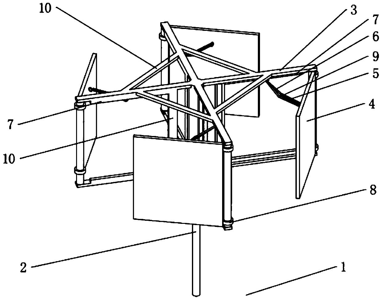
[0045] combine Figure 1-5 , differs from Embodiment 1 in that the blade 4 is hinged on the mounting frame 3 with a rotating shaft along the horizontal direction and is hinged on the inside of the top end of the mounting frame 3. When working, the blades 4 on both sides perpendicular to the wind direction, one piece in the wind close under the pressure of the wind, and the other sheet is blown up under the pressure of the wind, which also reaches the effect of embodiment one.

Embodiment 3

[0047] combine Image 6, the difference from the first embodiment is that the blade 4 is provided with an elastic window 11, and the elastic window 11 is installed with an elastic plate 12 larger than the elastic window 11, and the elastic plate 12 is arranged on the blade 4 close to the flange 7, the spring 13 is fixedly connected to the side of the elastic plate 12 away from the elastic window 11, and the end of the spring 13 away from the elastic plate 12 is fixedly connected to a fixed plate 14 fixedly installed on the blade 4 and the elastic plate 12 The spring 13 is in a compressed state when abutting on the blade 4 . In case of strong wind, the elastic window 11 can automatically open the elastic sheet 12 under the action of the spring 13, thereby reducing the pressure area of ​​the blade 4, thereby limiting the speed of the windmill 4 and thus limiting the maximum power. It is not necessary to use brakes to protect itself and avoid power generation The machine is over...

Embodiment 4

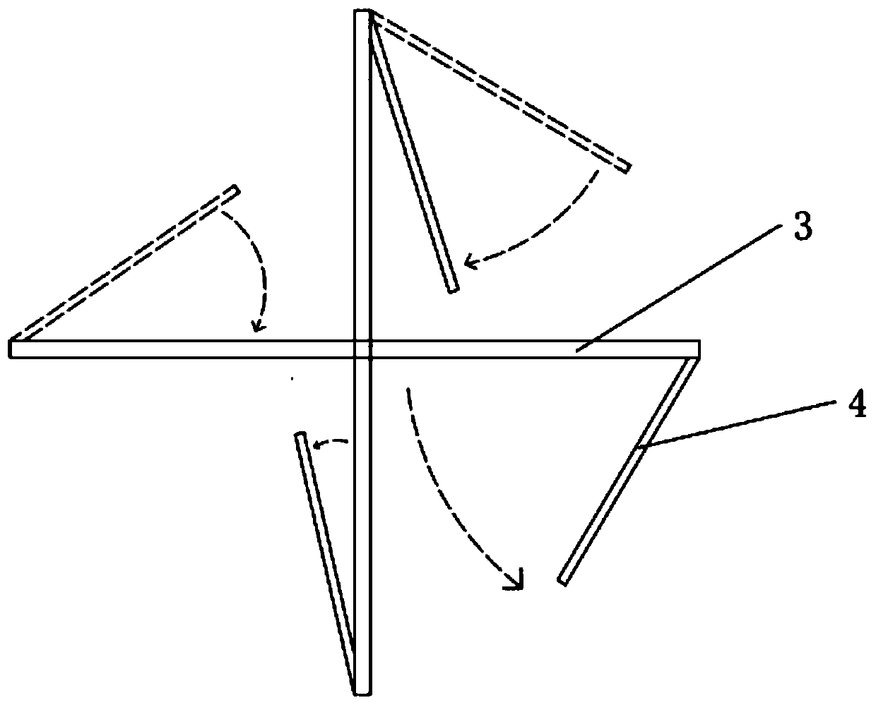
[0049] combine image 3 with Figure 7 The difference from Embodiment 1 is that a roller 15 is fixedly installed at the bottom of the end of the mounting frame 3 away from the support shaft 2, and an arc-shaped slide rail 16 that cooperates with the roller 15 when the blade 4 rotates is fixedly connected to the ground 1. , so that the opening and closing of the blade 4 is smooth, and the force at both ends can enhance the stability of the blade 4 .


PUM


Abstract

The embodiment of the invention discloses avertical axis and moving blades combined windmill. The windmill includes the ground, a supporting shaft, an installation frame and four blades, wherein the supporting shaft is fixedly installed on the ground, the installation frame is connected to the supporting shaft in a rotating mode and the four blades are evenly installed on the installation frame. The supporting shaft is usually placed vertically, the installation frame is in a square frame shape, and one sides of the blades are hinged to the installation frame. Included angles are formed between the blades and the installation frame, and every two opposite blades are arranged on the different sides of the installation frame. One sides of the blades are fixedly connected with tension springswhich are connected to the installation frame through ropes. According to the rotation direction, the windmill is divided into a downwind side and an upwind side, wherein the blades on the downwind side are automatically closed under the pressure of wind, and due to the vertical pressure of the wind, all wind energy is converted into mechanical energy. At the same time, the blades on the upwind side are blown open by the wind to form a set included angle with the wind direction. The maximum included angle between the blades and the installation frame is 60-70 degrees, force enabling the windmill to rotate forward can also be produced, and therefore, the moving blades can more effectively convert the wind energy into the mechanical energy.

Description

technical field [0001] The embodiment of the present invention relates to the technical field of wind power generation equipment, in particular to a combined vertical-axis movable blade windmill. Background technique [0002] A windmill, also called a wind turbine, is a power machine that converts wind energy into mechanical work. Broadly speaking, it is a thermal energy utilization engine that uses the sun as a heat source and the atmosphere as a working medium. [0003] Although there are many kinds of wind turbines, they can be summarized into two categories: 1. Horizontal axis wind turbines, where the rotation axis of the wind rotor is parallel to the wind direction; 2. Vertical axis wind turbines, where the rotation axis of the wind rotor is perpendicular to the ground or the direction of the airflow. [0004] The most important difference between vertical-axis wind turbines and horizontal-axis windmills is that typical horizontal-axis windmills require taller towers t...

Claims


Application Information

Patent Timeline
Patent Type & Authority Applications(China)
IPC IPC(8): F03D3/06F03D7/06F03D80/00
CPCF03D3/005F03D3/062F03D3/064F03D3/068F03D7/06F03D80/00Y02E10/74
Inventor 石峰石鹏飞
Owner 石峰
Why Eureka
Try Eureka