Power control valve and loader quantitative-variable hydraulic system

A power control valve and hydraulic system technology, which is applied in pump control, mechanical equipment, machine/engine, etc., can solve the problems of insufficient power input and large proportion of input power in the walking system, and achieve a wide range of power adjustment and reduce the size of the pump. Displacement, the effect of improving the life of components

Active Publication Date: 2014-11-19
GUANGXI LIUGONG MASCH CO LTD
View PDF5 Cites 9 Cited by
  • Summary
  • Abstract
  • Description
  • Claims
  • Application Information

AI Technical Summary

Problems solved by technology

[0007] The purpose of the present invention is to provide a loader in view of the shortcomings of the variable pump in the fixed variable hydraulic system of the existing loader that the input power of the pump accounts for a large proportion of the input power of the pump under heavy load due to the output of the rated displacement, which leads to insufficient power input of the walking system. Power control valve used in constant variable hydraulic system and loader constant variable hydraulic system with the power control valve

Method used


Image

  • Power control valve and loader quantitative-variable hydraulic system
  • Power control valve and loader quantitative-variable hydraulic system

Examples


Embodiment Construction

[0027] Specific embodiments are described below with reference to the accompanying drawings.

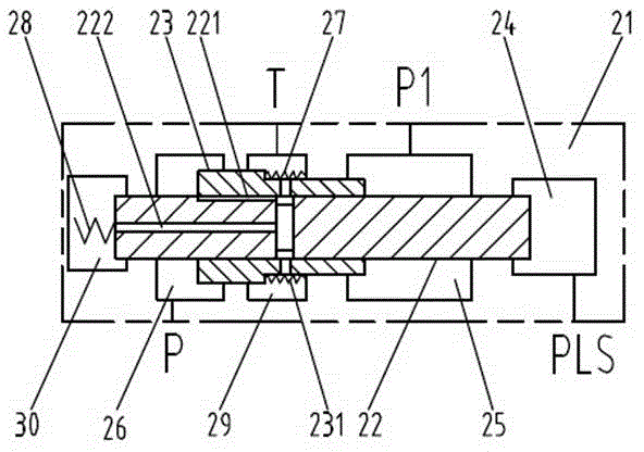
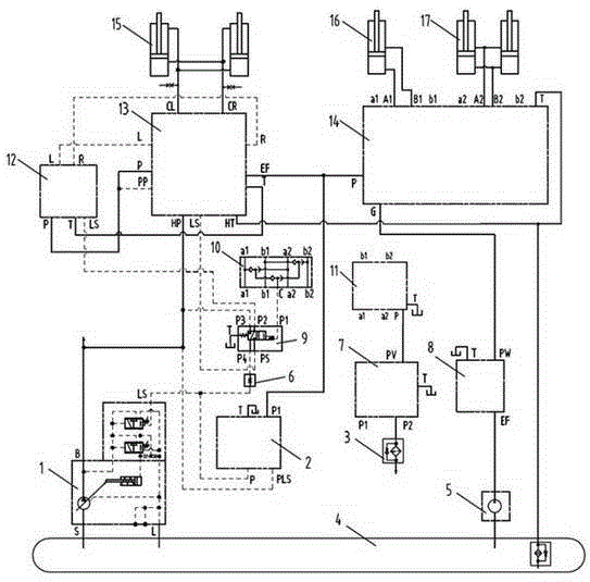
[0028]In this embodiment, the fixed variable hydraulic system of the loader includes a load sensitive variable pump 1, a quantitative pump 5, a distribution valve 14, a pilot valve 11, a shuttle valve 10, a working oil cylinder, a fuel tank 4, a hydraulic steering system, and a two-position four-way valve. 9. Power control valve 2, the working cylinder includes a bucket cylinder 16, a boom cylinder 17, and the hydraulic steering system includes a load-sensitive steering gear 12, a load-sensitive flow amplifying valve 13, and a steering cylinder 15; the load-sensitive steering gear 13 and the load-sensitive flow Amplifying valve 13 is connected and controls steering cylinder 15 connected to load-sensing flow amplifying valve 13 via load-sensing flow-amplifying valve 13 , the main oil port of load-sensing variable pump 1 is connected to load-sensing flow-amplifying valve 13 , and load-s...


PUM


Abstract

The invention relates to a loader quantitative-variable hydraulic system and aims to overcome the defect that the input power of a variable pump in the existing quantitative-variable hydraulic system accounts for a large amount. The invention further discloses a power control valve. A first cavity in a valve body is communicated with a port PLS and acts on the right end of a main valve element. A valve element spring is disposed at the left end of the main valve element. A valve sleeve sleeves the main valve element. A second cavity is communicated with a port P1 and acts on the right end of the valve sleeve. A third cavity is communicated with a port P and acts on the left end of the valve sleeve. A valve sleeve spring provides leftward elastic force for the valve sleeve. An oil drainage passage communicated with the third cavity and a port T are formed in the main valve element and the valve sleeve. When the main valve element moves leftwards relative to the valve sleeve, the oil drainage passage is communicated. When the main valve element moves leftwards relative to the main valve element, the oil drainage passage is reduced or closed. The power control valve has the advantages that the valve sleeve and the main valve element form a follow-up mechanism, the input power of the variable pump of the loader quantitative-variable hydraulic system can be controlled by the power control valve, and the input power is prevented from accounting for a large amount.

Description

technical field [0001] The invention relates to a loader hydraulic system, in particular to a power control valve used in a loader constant variable hydraulic system and a loader constant variable hydraulic system with the power control valve. Background technique [0002] At present, the commonly used loader hydraulic systems include quantitative hydraulic system, fixed variable hydraulic system and full variable hydraulic system. The technical characteristics of each hydraulic system are as follows: [0003] Quantitative hydraulic system has large power loss, such as throttling loss, overflow loss, and loss along the way, and low energy conversion efficiency, but the system structure is simple and the cost is low; [0004] The full variable hydraulic system has no overflow loss, and has the lowest throttling loss and loss along the way, high energy conversion efficiency and good energy saving effect, but the hydraulic components are expensive, rely on imports, and have hi...

Claims


Application Information

Patent Timeline
Patent Type & Authority Applications(China)
IPC IPC(8): E02F9/22F04B49/22
Inventor 梁振国莫雄超范武德沈洪伟
Owner GUANGXI LIUGONG MASCH CO LTD
Why Eureka
Try Eureka