
Bearning mechanism

A technology of bearings and bearing parts, which is applied to sewing machine components, needle seats for sewing machines, textiles and papermaking, etc. It can solve the problems that pins cannot maintain hardness or size, it is difficult to reduce costs, and high processing costs are easy to process, The effect of suppressing processing costs and reducing costs

Inactive Publication Date: 2006-11-01
JUKI CORP
View PDF2 Cites 0 Cited by
  • Summary
  • Abstract
  • Description
  • Claims
  • Application Information

AI Technical Summary

Problems solved by technology

Therefore, even if the base material is hardened by quenching before the chromium nitride coating is formed, the base material is softened by the tempering effect, so that the pin cannot maintain the desired hardness or size.
Therefore, it is also considered to use high-speed steel (SKH) and die steel (SKD) tempered at a temperature (550°C) higher than the temperature (400°C to 500°C) at which the chromium nitride layer is formed as the base material, but , due to the high processing costs compared with low carbon alloy steel and bearing steel, it is difficult to achieve cost reduction

Method used


Image

  • Bearning mechanism
  • Bearning mechanism
  • Bearning mechanism

Examples


Embodiment Construction

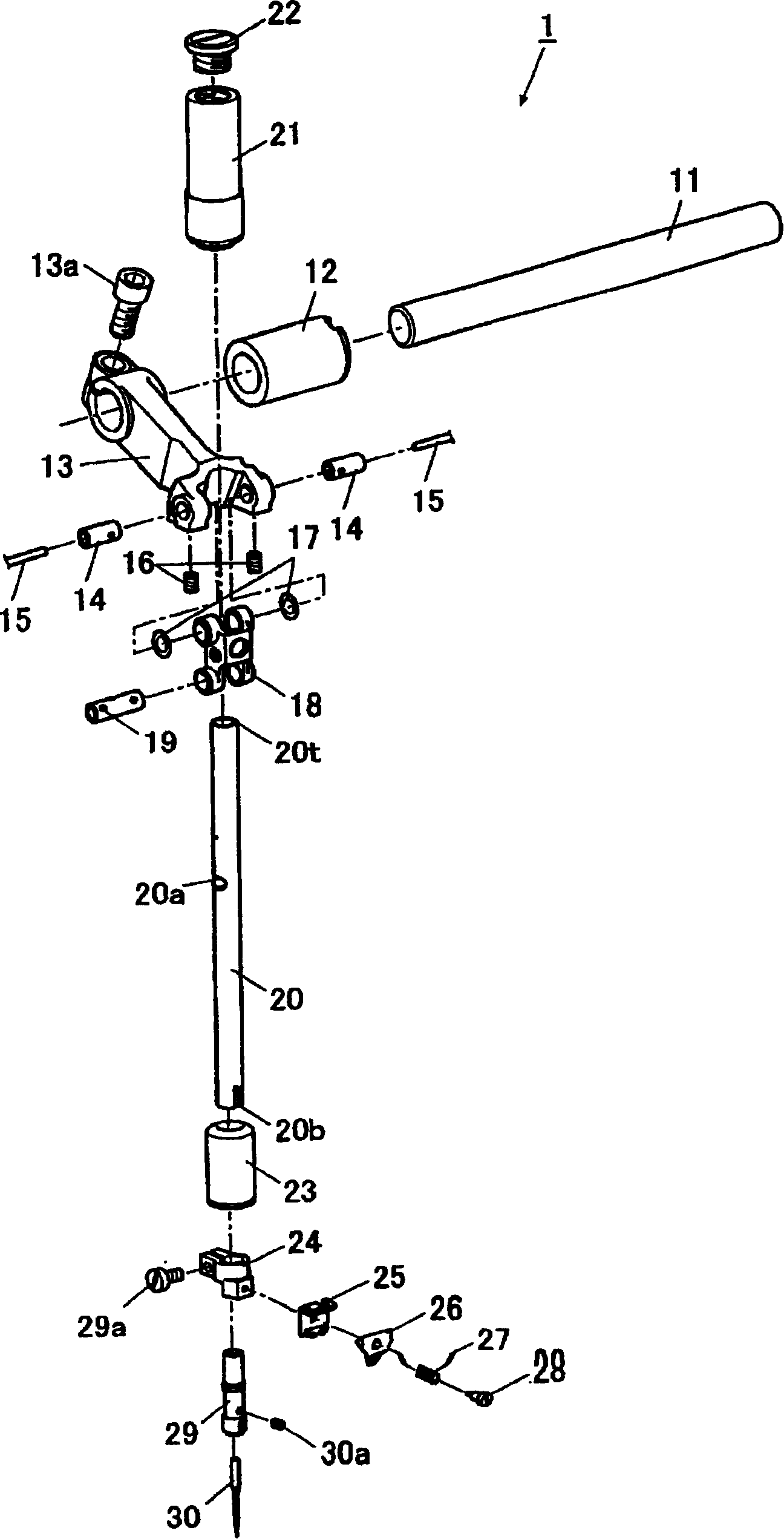
[0043] Next, the best mode of the bearing mechanism, the needle bar driving mechanism of the sewing machine and the looper mechanism of the sewing machine according to the present invention will be described with reference to the accompanying drawings. In addition, in this embodiment, the needle bar drive mechanism of the sewing machine which has a bearing mechanism, and the looper mechanism of a sewing machine are demonstrated.

[0044] (needle bar drive mechanism of sewing machine)

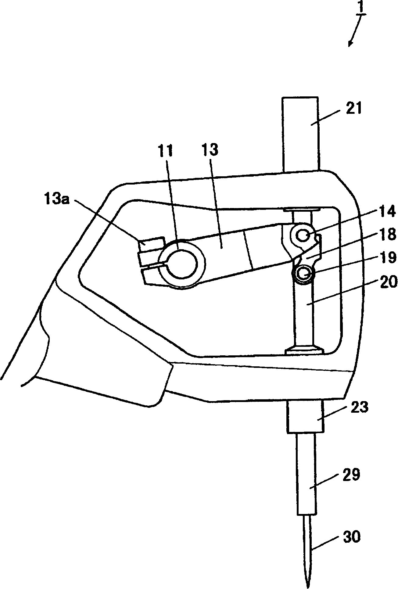
[0045] Such as figure 1 and figure 2 As shown, the needle bar driving mechanism 1 of the sewing machine (hereinafter referred to as the needle bar driving mechanism 1) has a needle bar driving shaft 11 that transmits the driving force from the sewing machine motor and swings. On one end of the needle bar driving shaft 11, a bolt 13a is equipped with drive shaft bearing bush (metal) 12 and needle bar drive handle 13. The needle bar driving handle 13 is formed to extend in a direction substant...


PUM


Abstract

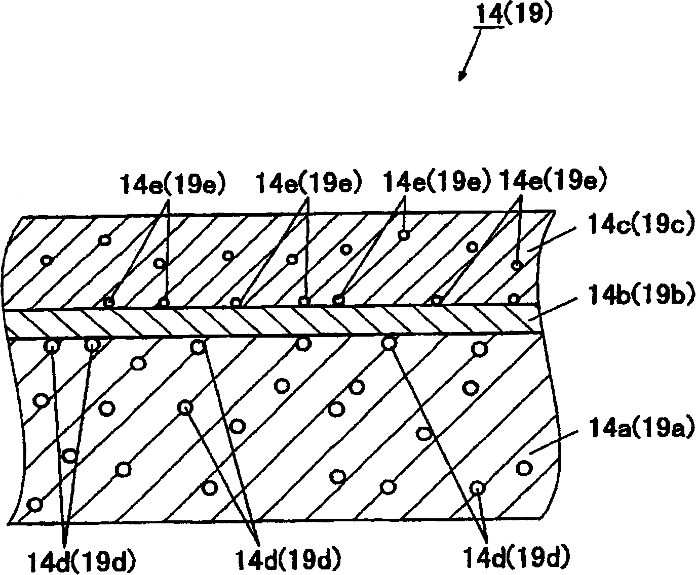
The present invention provides a bearing mechanism that can reduce the cost of components and can improve wear resistance and sintering resistance even under conditions where the supply of lubricating oil is restricted. A needle bar drive mechanism (1) of a sewing machine includes: a needle bar drive shaft (11) that transmits the drive of the sewing machine motor and swings; A handle (13); a needle bar drive link (18) rotatably connected to the needle bar drive handle through a first pin (14); rotatably connected to the needle bar drive link through a second pin (19), And the needle bar (20) holding the needle (30) at the lower end is driven by the sewing machine motor in the up-down direction, wherein the first pin and the second pin are more tempered than the base material (14a, 19a). In a low temperature environment, chromium nitride layers (14c, 19c) are formed on the surface.

Description

technical field [0001] The invention relates to a bearing mechanism. Background technique [0002] Conventionally, devices driven at high speeds have mechanisms in which components slide at high speeds. For example, a sewing machine includes a needle bar drive mechanism, an upper looper mechanism, and the like. In this needle bar driving mechanism, the needle bar driving handle is connected to the needle bar driving shaft connected to the sewing machine motor, and the needle bar driving link is rotatably connected to the front end of the needle bar driving handle through a pin. . The needle bar is rotatably coupled to the needle bar drive link via the pin, and the needle through which the upper thread has passed is held at the tip of the needle bar. [0003] These parts are formed of low-carbon alloy steel or bearing steel with relatively low processing costs. In order to prevent fretting wear or sintering of the sliding contact surface, the oil supply mechanism is used t...

Claims


Application Information

Patent Timeline
Patent Type & Authority Applications(China)
IPC IPC(8): D05B55/00
Inventor 应性宝平野靖明饭岛秀和
Owner JUKI CORP
Learn More