Bidirectional multi-frequency integrated antenna
An integrated antenna and antenna technology, applied in the direction of antenna, antenna array, radiating element structure, etc., can solve the problems of large size, unusable, antenna application restrictions, etc., and achieve the effect of small size, convenient control, and simple structure
- Summary
- Abstract
- Description
- Claims
- Application Information
AI Technical Summary
Problems solved by technology
Method used
Image

Examples
Embodiment 1
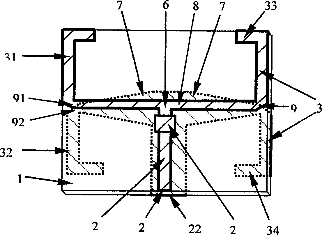
[0024] A bidirectional multi-frequency integrated antenna used in a communication system, comprising a dielectric substrate 1, on which two surfaces of the dielectric substrate 1 are respectively provided with a microstrip transmission line 21, a microstrip ground 22 and at least two symmetrical dipole antennas 3, The other ends of the microstrip transmission line 21 and the microstrip ground 22 are respectively connected with a T-shaped branch 6 and connected with the unbalanced input port of the T-shaped branch 6 respectively. A symmetrical dipole antenna in each pair of symmetrical dipole antennas is connected with the T-shaped dipole antenna. The balanced output port of the branch is connected, and the other symmetrical dipole antenna is connected with the other balanced output port of the T-shaped branch. Any pair of vibrators forming the symmetrical dipole antenna are respectively located on the two surfaces of the dielectric substrate 1 and are respectively located on the...
Embodiment 2
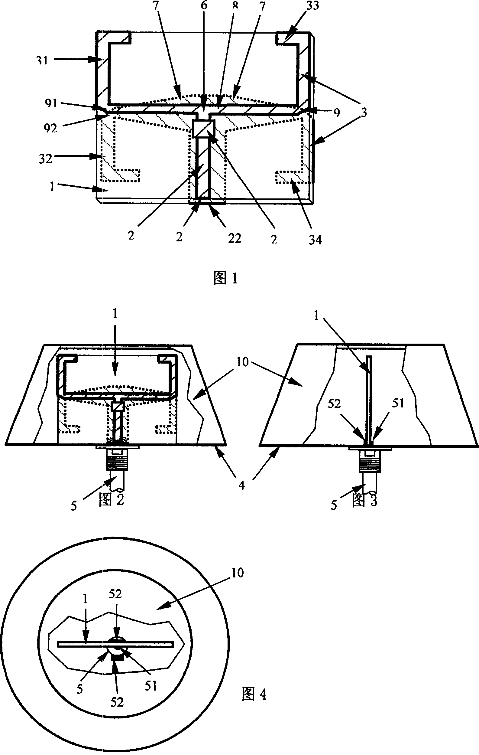
[0027] A two-way antenna working in the WLAN 802.11b / g frequency band is shown in Figure 5, and the microstrip dielectric substrate of the antenna and its feed circuit and printed antenna are shown in Figure 1. The dielectric substrate is a glass fiber-polytetrafluoroethylene double-sided copper-clad board with a thickness of 1mm and a dielectric constant of 2.65. The signal feed-in point is connected in such a way that the inner conductor 51 of the coaxial cable 5 is connected to the feeder input end 21, the outer conductor 52 of the coaxial cable 5 is connected to the microstrip ground 22 of the feeder input end, and is also welded to the metal ground plane 4 at the same time. Together, to ensure good grounding performance, see Figure 1, Figure 2, Figure 4 and Figure 4, the radome 10 is used to protect the antenna and beautify it. See Figure 9, Figure 10 and Figure 11 for the direction diagram and the test results of the S11 frequency response characteristic representing the...
Embodiment 3
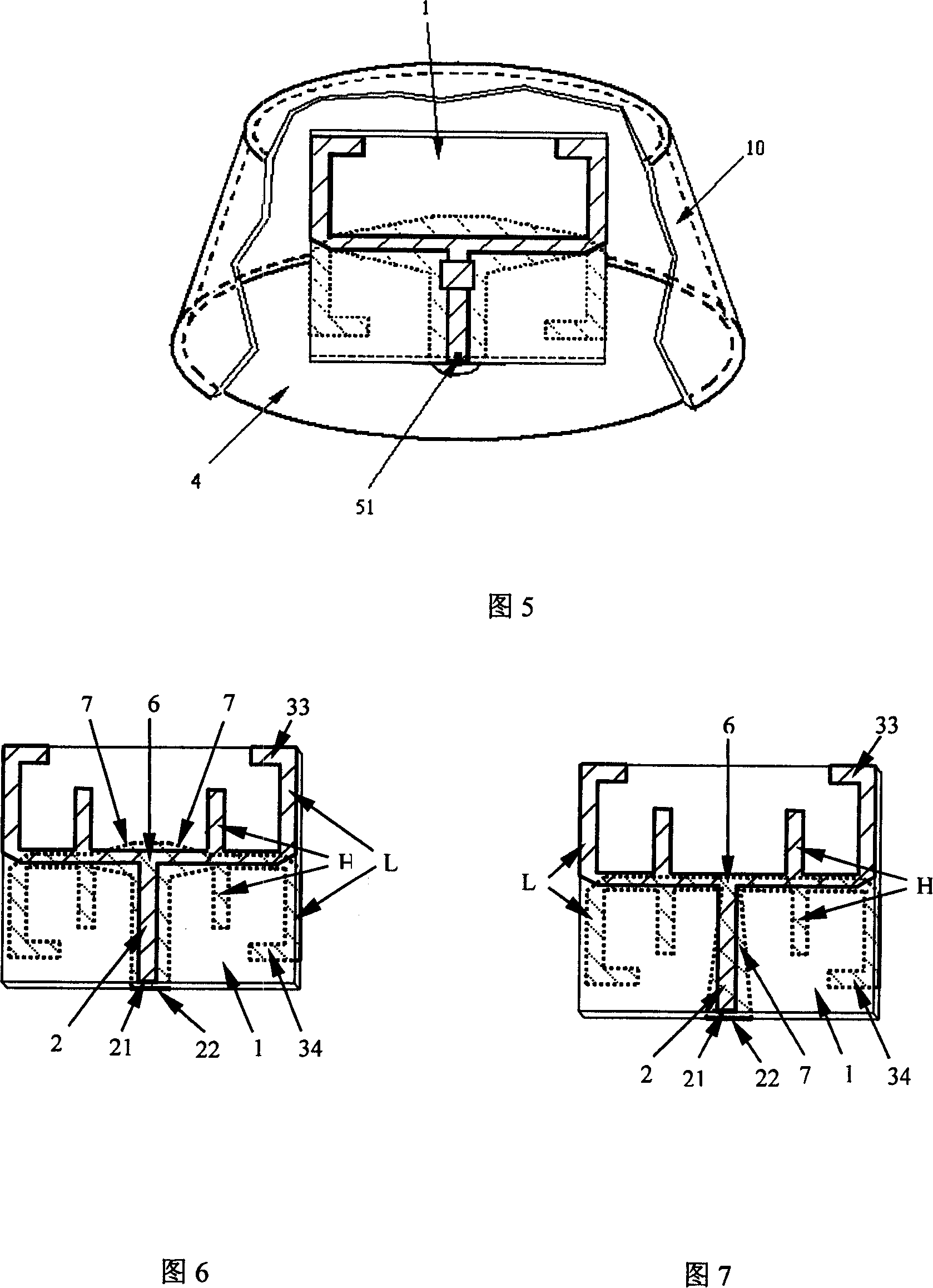
[0029] The feed and vibrator structure of a bidirectional dual-frequency dual-mode antenna is shown in FIG. 6 . On the microstrip dielectric substrate 1, there are feeder circuits 2, two groups of vibrator antennas working at different frequencies (4 pairs in total) H (2 pairs), L (2 pairs), T-shaped branch 6, balanced-unbalanced transformation Device 7, a group of dipole antennas H with high frequency is placed between a group of dipole antennas L with low frequency, and the ends of the dipole arms of a group of low frequency antennas can be folded 33, 34 at 90° to reduce the size of the antenna. The balun 7 can also be implemented on the main feeder before the T-shaped branch using the structure shown in FIG. 7 , and the signals of the two frequency bands can be fed to the antenna from 21 and 22 through a coaxial cable. The method of connecting the antenna to the coaxial cable 5 and the metal ground plane 4 is the same as that of the first embodiment, and the antenna is plac...
PUM
 Abstract
Description
Claims
Application Information
 - Generate Ideas
- Intellectual Property
- Life Sciences
- Materials
- Tech Scout
- Unparalleled Data Quality
- Higher Quality Content
- 60% Fewer Hallucinations
Browse by: Latest US Patents, China's latest patents, Technical Efficacy Thesaurus, Application Domain, Technology Topic, Popular Technical Reports.
© 2025 PatSnap. All rights reserved.Legal|Privacy policy|Modern Slavery Act Transparency Statement|Sitemap|About US| Contact US: help@patsnap.com