
Two-dimensional image area positioning method based on grating projection

A grating projection, two-dimensional image technology, applied in the direction of using optical devices, photogrammetry/video surveying, measuring devices, etc.

Inactive Publication Date: 2006-10-18
HAIAN COUNTY SHENLING ELECTRICAL APPLIANCE MFG +1
View PDF0 Cites 17 Cited by
  • Summary
  • Abstract
  • Description
  • Claims
  • Application Information

AI Technical Summary

Problems solved by technology

[0025] 4) Noise from mechanical devices
[0027] 5) Noise caused by the grating sheet

Method used


Image

  • Two-dimensional image area positioning method based on grating projection
  • Two-dimensional image area positioning method based on grating projection
  • Two-dimensional image area positioning method based on grating projection

Examples


Embodiment Construction

[0060] A 2D image area localization method based on raster projection for fringe image coding:

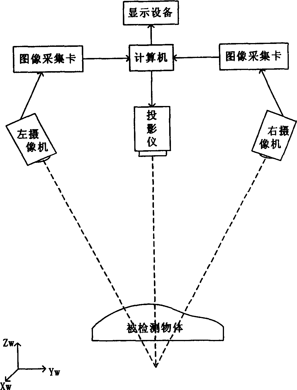
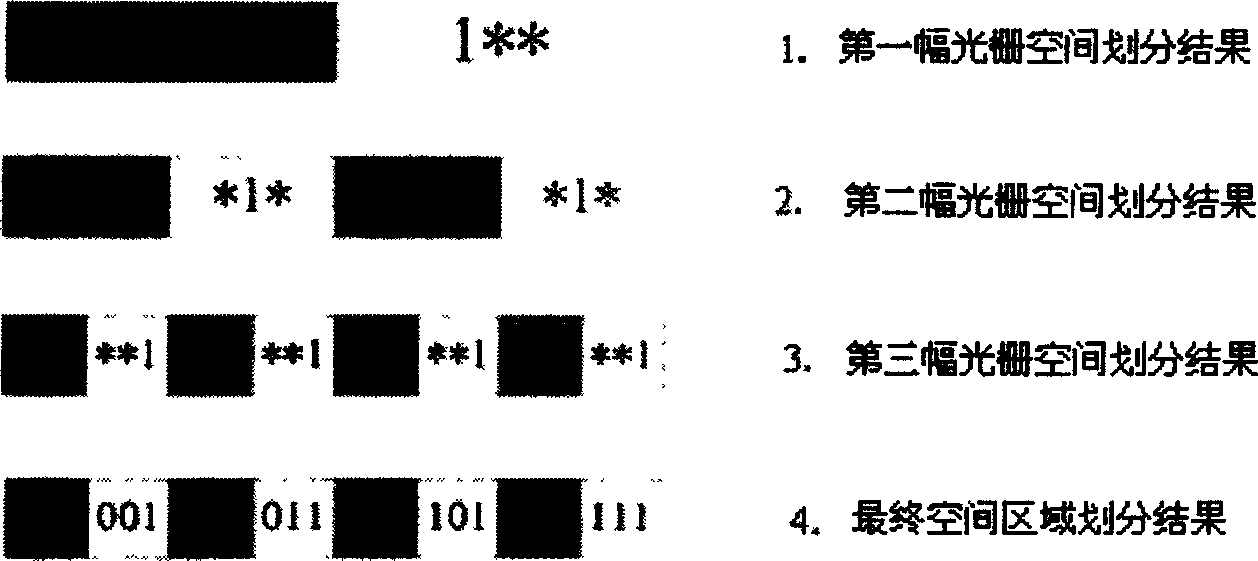
[0061] 1) Use the CCD camera to first take a picture of the measured object as a reference picture, and then project a set of thick and thin gratings onto the object successively by the projection device, and each time a grating is projected, the CCD camera will take a picture of it, The above-mentioned coarse grating is a grating with a single stripe width greater than 10 pixels. There are two black and white stripes in the first coarse grating image, and the second coarse grating image equally divides the black and white stripes in the first image to obtain 4 alternating black and white stripes. stripes, and so on, the nth rough raster picture equally divides the stripes in the n-1th rough raster picture, and 2 n Black and white alternating stripes, the specific value of n is determined by the parameters of the CCD camera. For a high-resolution CCD camera, the corresponding value...


PUM


Abstract

The two-dimensional image area positioning method based on the grating projection can determine the source and characteristic of image noise for noise inhibition. The method includes the following steps: taking the datum picture with CCD camera before projecting one coarse set or fine set of grating to the object before taking one image and obtaining coarse positioning image through threshold parting, image filtering, etc; filtering the image with fine grating image to obtain the fine grating grey image; non-interlaced traversing the pixels in the coarse positioning image and processing in compensation algorithm to divide the measured object space into narrow zonal areas and obtain the corresponding coarse positioning result image; and superposing the above boundary information onto all the fine grating grey images to be analyzed, non-interlaced traversing, performing quadratic curve fitting and final superposing the extreme points of all the fine grating grey images as the ultimate object space dividing result.

Description

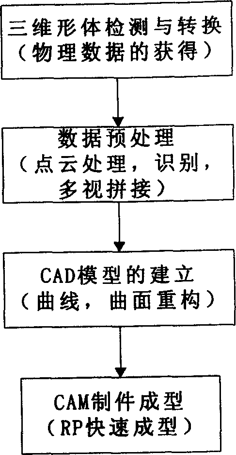
technical field [0001] The invention relates to a two-dimensional image area positioning method when a grating projection device is used to perform three-dimensional reconstruction on an object, in particular to a two-dimensional image area positioning method based on grating projection. Background technique [0002] Reverse Engineering (Reverse Engineering, RE) technology is a new technology that appeared in the field of advanced manufacturing in the late 1980s. Most of the research on reverse engineering mainly focuses on the reverse reconstruction of the object, that is, the reconstruction of the CAD model of the product object and the manufacturing of the final product, which is called "reverse engineering of the object". Its process structure see figure 1 . [0003] The grating projection method is one of the reverse engineering technologies of real objects. It has the characteristics of completely non-contact detection process, high spatial resolution of data, and on...

Claims


Application Information

Patent Timeline
Patent Type & Authority Applications(China)
IPC IPC(8): G01B11/03G01C11/00
Inventor 达飞鹏金亚盖绍彦
Owner HAIAN COUNTY SHENLING ELECTRICAL APPLIANCE MFG
Learn More