Guide wire
A technology for guide wires and guide wires, which is applied in catheters, guide wires, etc., can solve the problems of troublesome connection of guide wires, failure to improve the joint strength of guide wires, difficulty in obtaining torque transmission, etc., and achieve improved safety , Excellent operability, and the effect of preventing bending (bending) or twisting
Inactive Publication Date: 2010-11-10
TERUMO KK
View PDF2 Cites 3 Cited by
- Summary
- Abstract
- Description
- Claims
- Application Information
AI Technical Summary
Problems solved by technology
Although such a guide wire can be equipped with guide wire parts with desired characteristics on its front end side and base end side, but because it connects the two guide wire parts through a tubular connecting member, there is a problem that the two guide wire parts cannot be improved. The joint strength is difficult to obtain sufficient torque transmission
In addition, there is also a problem in manufacturing that the connection work of the guide wire part is troublesome.
Method used
View moreImage
Smart ImageViewing Examples
Examples
Embodiment Construction
Login to View More PUM
 Abstract
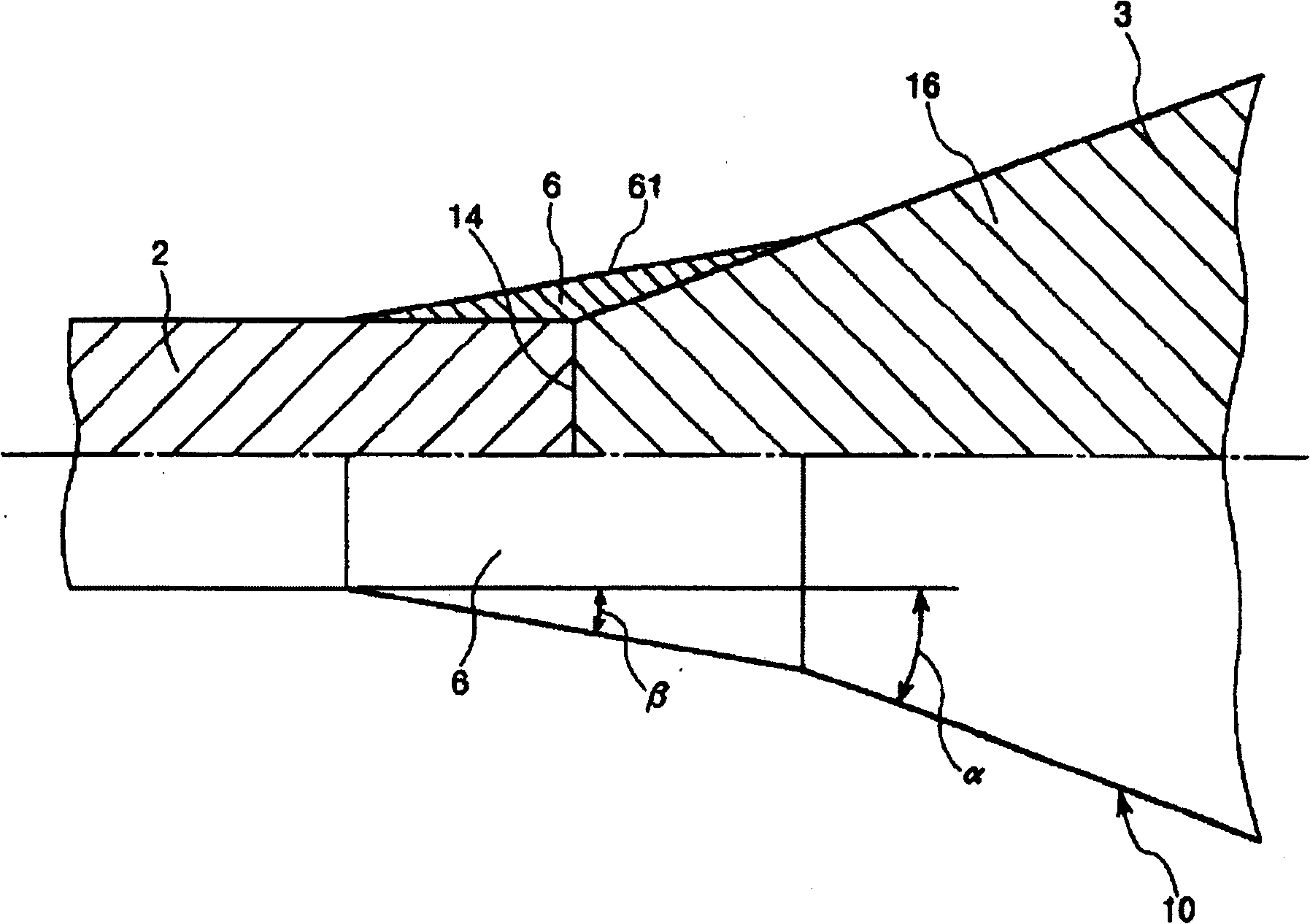
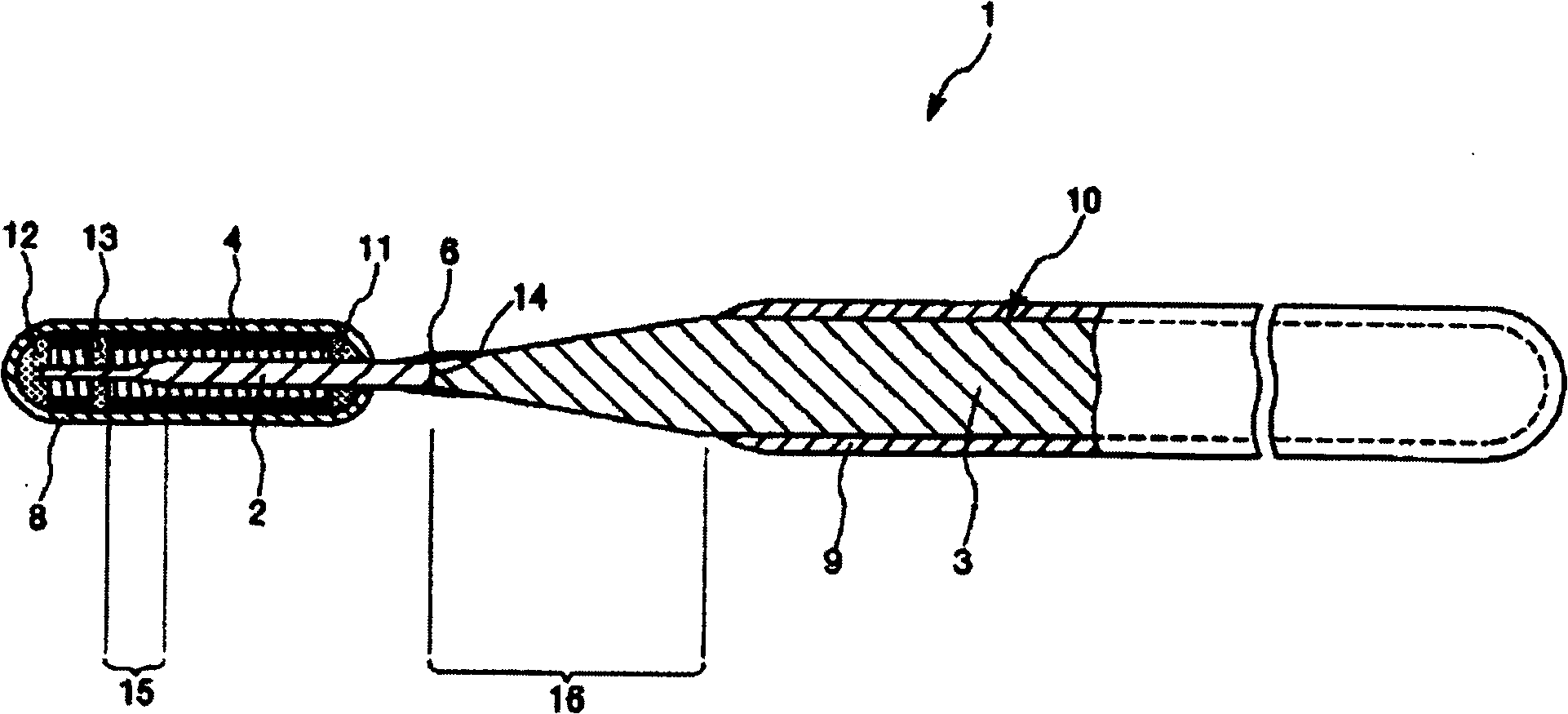
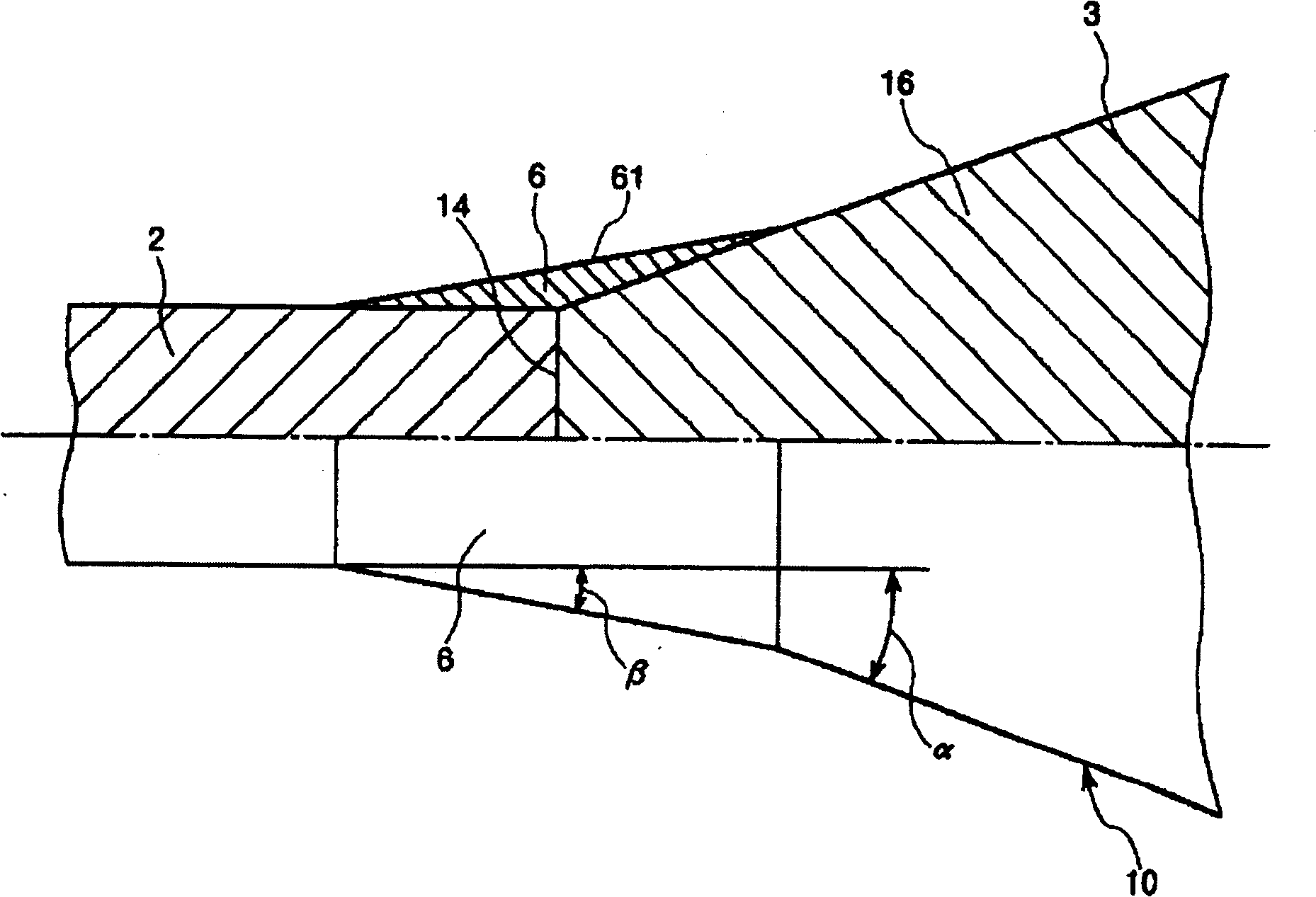
The invention relates to a guide wire which can confirm the flexibility of front end with better operation, wherein the connect strength between first and second guide wires are be improved; it comprises a main body with the first guide wire part at the front end and the second guide wire part at the base of first guide wire; the outer circumference of front end of first guide wire has the coil with X-radio contrast; the base of first guide wire has constant valve of outer diameter along length direction; the front end of second guide wire is best formed by the taper that increasing from front end to base; the outer diameter of base of first guide wire is best the same as the front of second guide wire; the outer diameters of two guide wires via one end surface are welded; the circumference of connection part is best formed with metallic cover layer, to release the angle difference between the circumference of the base of first guide wire and the outer circumference of taper part.
Description
guide wire technical field The present invention relates to a guide wire, and more particularly to a guide wire used for guiding a catheter into body cavities such as blood vessels and bile ducts. Background technique Catheters are used in the treatment of difficult-to-operate sites such as PTCA (Percutaneous Transluminal Coronary Angioplasty), or in treatments aimed at reducing damage to the human body, or in examinations such as cardiac angiography , the guide wire is used to guide the catheter. Regarding this guide wire for PTCA, when using it, in the state where the tip of the guide wire protrudes from the tip of the balloon catheter, the guide wire and the balloon catheter are inserted into the vicinity of the narrowed part of the blood vessel at the target site, and the guide wire Guide the tip of the balloon catheter to the vicinity of the narrowed part of the blood vessel. In addition, in the treatment of lesions of the bile duct or pancreatic duct, a guide wire...
Claims
Login to View More Application Information
Patent Timeline
 Patent Type & Authority Patents(China)
IPC IPC(8): A61M25/09A61M25/01
Inventor 田野丰梅野昭彦
Owner TERUMO KK
Features
- R&D
- Intellectual Property
- Life Sciences
- Materials
- Tech Scout
- Unparalleled Data Quality
- Higher Quality Content
- 60% Fewer Hallucinations
Learn More Browse by: Latest US Patents, China's latest patents, Technical Efficacy Thesaurus, Application Domain, Technology Topic, Popular Technical Reports.
© 2025 PatSnap. All rights reserved.Legal|Privacy policy|Modern Slavery Act Transparency Statement|Sitemap|About US| Contact US: help@patsnap.com


