
Buried reflux casing type circulating geothermal heat exchanger and use thereof

A heat exchange device, sleeve-type technology, applied in the field of buried return flow sleeve-type circulation geothermal heat exchange device, can solve the increase of ground hole drilling costs and related material costs, small footprint of spiral coils, and stable system In order to achieve the effect of expanding the scope of project adaptation, reducing the amount of construction and reducing the cost of pile foundation

Inactive Publication Date: 2006-10-04
潘戈
View PDF0 Cites 10 Cited by
  • Summary
  • Abstract
  • Description
  • Claims
  • Application Information

AI Technical Summary

Problems solved by technology

Therefore, the soil buried tube heat pump system maintains the advantages of the groundwater source heat pump using the earth as a cold and heat source, and at the same time does not need to extract groundwater as a heat transfer medium. It is a sustainable building energy-saving new technology with greater development prospects. , The buried tube type circulation geothermal heat exchange device can be used as a front-end coupling part of the soil buried tube heat pump system. Generally, according to the buried tube method of the buried heat exchanger, it can be divided into: horizontal buried tube, vertical buried tube and spiral coil tube , this kind of ground source heat pump system has relatively high requirements on the material and geological structure of the soil heat exchanger. Among them, the horizontal buried pipe occupies a large area and needs to be excavated. The influence of factors is large, and the stability of the system is low; the vertical buried pipe is less affected by the surface environment temperature, but the buried pipe is deep. The corresponding ground hole drilling costs and related material costs increase. The spiral coil covers a small area and relatively small investment, but it needs to be excavated. The heat transfer effect is between the former two, not as good as the vertical buried tube. The investment of tubular heat pump system is higher than that of other ground source heat pump methods, so this kind of system is generally only suitable for residential single buildings with relatively small area, and it is relatively difficult to apply in large-scale projects

Method used


Image

  • Buried reflux casing type circulating geothermal heat exchanger and use thereof
  • Buried reflux casing type circulating geothermal heat exchanger and use thereof
  • Buried reflux casing type circulating geothermal heat exchanger and use thereof

Examples


Embodiment Construction

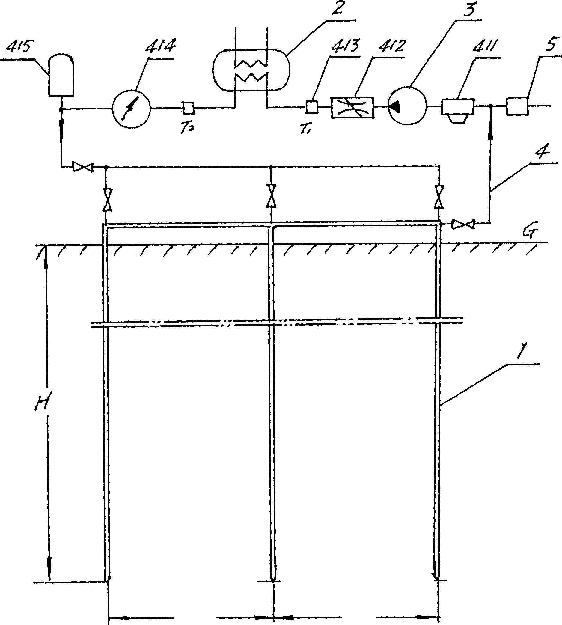
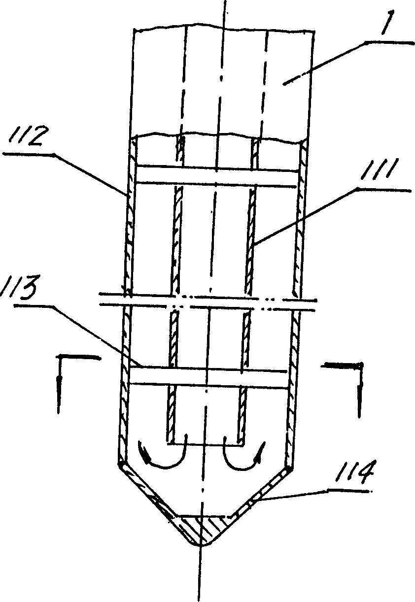
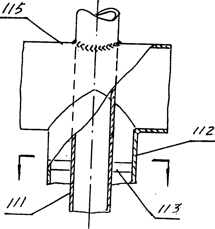
[0014] according to figure 1 As shown, one of the embodiments of the buried return casing type circulating geothermal heat exchange device of the present invention is composed of a buried pipe 1, a heat exchange unit 2, a circulation pump 3, a circulation pipeline 4, a moisturizing seepage pipe 5, and a heat-carrying medium. . Among them, the buried pipe adopts such as figure 2 The buried return sleeve with the inner pipe fixed in the outer pipe as shown has a structure including an inner pipe 111, an outer pipe 112, a holder 113 and a cone top 114 welded to the outer pipe. In addition, the buried The ground pipes are also connected to each other via a manifold 115 , and the circulation pipeline 4 includes a decontamination device 411 , a flow regulating valve 412 , a temperature sensor 413 , a flow meter 414 , and an accumulator 415 . Buried pipes, heat exchange units, circulation pumps, circulation pipelines, etc. constitute a closed geothermal heat exchange loop.

[001...


PUM


Abstract

The invention discloses an underground reflux tube circulating geothermal energy exchanging device, which comprises the following parts: underground pipe, heat exchanging unit, circulating pump, heat-loading dielectric and circulating loop, wherein the underground pipe is underground reflux housing pipe of inner pipe in the outer pipe; the geothermal energy exchanging circulating loop provides heat or cold source for dielectric, which forms underground circulation loop through reflux pipe bottom, interlayer of inner and outer pipe or underground circulation.

Description

technical field [0001] The invention belongs to the field of air-conditioning energy saving and renewable energy utilization, and in particular relates to the technology and application of a soil-buried pipe type buried return sleeve type circulation geothermal heat exchange device. Background of the invention [0002] The water source and soil on the earth's surface are a huge solar heat collector, collecting 47% of the sun's energy, which is more than 500 times the energy used by human beings every year. The ground source heat pump system is a high-efficiency building energy-saving air-conditioning system that uses underground shallow ground energy, including groundwater, soil, or surface water, to provide both heating and cooling. By inputting a small amount of high-grade electric energy, low temperature The transfer of potential energy to high-temperature potential energy. Among them, water source heat pump is a heating and air conditioning system that uses the earth's s...

Claims


Application Information

Patent Timeline
Patent Type & Authority Applications(China)
IPC IPC(8): F24J3/08F24F5/00
CPCY02E10/10Y02B10/40
Inventor 潘戈
Owner 潘戈
Learn More