
Kinetic energy illuminator

A light-emitting device and kinetic energy technology, which is applied in the field of optoelectronic technology and products, can solve problems such as environmental pollution and limit the service life of products, and achieve the effects of low cost, improved energy conversion efficiency, and convenient power transmission

Inactive Publication Date: 2006-09-20
AUTOMATIC ENG RES & MFG CENT GUANGDONG SCI ACAD
View PDF0 Cites 10 Cited by
  • Summary
  • Abstract
  • Description
  • Claims
  • Application Information

AI Technical Summary

Problems solved by technology

The existing technology needs to equip each electronic light-emitting device with a small battery as the driving energy, which not only limits the service life of the product, but also causes huge pollution to the environment after being discarded

Method used


Image

  • Kinetic energy illuminator
  • Kinetic energy illuminator
  • Kinetic energy illuminator

Examples


Embodiment 1

[0054] Example 1: Kinetic Energy Luminous Shoes

[0055] see Figure 4~7 , This embodiment is applied to light-emitting shoes, and the PZT piezoelectric power generation transducer 1 is placed on the heel of the shoe to make it work in a forced vibration mode, and two groups of light-emitting diodes 2 connected in parallel are connected. When walking, the heel of the foot forces the transducer to vibrate forcibly, and sends out an alternating current consistent with the frequency of walking, and alternately lights up the anti-parallel light-emitting diode groups 2 . For a schematic diagram of the device, see Figure 4 , PZT piezoelectric power generation transducer structure see Figure 5 and Figure 6 , which includes a combined elastic shell 11 and a rigid shell 15, the shell is provided with electrodes 12, PZT ceramics 13, substrate 14 and buffer material 16, the circuit connection please refer to Figure 7 .

[0056] In this embodiment, three steps of transformation, ...

Embodiment 2

[0058] Example 2: Vibrating light keychain

[0059] see Figure 9 , the present embodiment of the piezoelectric power converter works in a free impact state. Through the free impact of the small steel ball 33 in the key chain on the piezoelectric element 31, the conversion of vibration energy is realized, and the LED 32 outside the key chain is lit.

Embodiment 3

[0060] Example 3: Vibrating and luminous bouncing ball

[0061] see Figure 10 , the present embodiment piezoelectric generator converter works in free vibration state. The length of the piezoelectric generating transformer 41 is slightly smaller than the diameter of the inner casing, so that it can move freely in the inner casing. Through the free collision and friction between the piezoelectric power generation converter 41 and the inner wall of the transparent rigid plastic inner shell 43, it can freely vibrate to realize the conversion of vibration energy, light up the light-emitting diode 42 installed on the piezoelectric power generation converter 41, and wrap it outside The transparent elastic rubber layer 44 is used to add a luminous effect to the traditional toy bouncing ball.


PUM


Abstract

Illuminator of using kinetic energy includes piezoelectric generating transducer and luminous element light emitting diode connected to each other. The piezoelectric generating transducer uses PZT piezoelectric ceramic as transduction material. The illuminator of using kinetic energy further includes transforming storage connected to piezoelectric generating transducer as well as flashing light sequence control part, which is connected to luminous element, for controlling time sequence of luminescence. The disclosed illuminator of using kinetic energy uses parasitical energy to glow, possessing features of lightweight, small size, low cost, relative high output electric quantity, and convenient transmission of electric energy.

Description

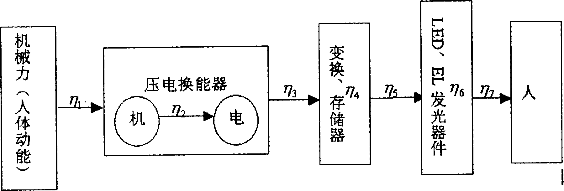
【Technical field】 [0001] The invention relates to the field of optoelectronic technology and products, in particular to a kinetic light emitting device. 【Background technique】 [0002] The use of kinetic energy to provide energy has actually had a fairly long history of application. Such as hand-operated generators, piezoelectric igniters, friction bicycle lights, etc., but the above application methods require specific manual methods to drive specific devices to work. For how to use the energy provided by kinetic energy more efficiently and conveniently, foreign countries are currently actively conducting research and application in this area. [0003] A research group at the Delft University of Technology in the Netherlands launched a research program called "Personal Energy System" to carry out research on human energy applications [references: R.J.Kuipers, "Engineering a human powered mp3 player", Graduation report, DelftUniversity of Technology, Delft, 2003.], they an...

Claims


Application Information

Patent Timeline
IPC IPC(8): H02N2/18H01L41/113H05B37/02H02J15/00
CPCY02B20/42Y02B20/40Y02E60/16
Inventor 李海生
Owner AUTOMATIC ENG RES & MFG CENT GUANGDONG SCI ACAD
Learn More