Optical pick-up apparatus
一种光拾取装置、激光的技术,应用在光束引导装置、集成光学头装置、光束源等方向,能够解决无法顺利地导出再生信号错误信号、构成复杂化、部件件数增加等问题
- Summary
- Abstract
- Description
- Claims
- Application Information
AI Technical Summary
Problems solved by technology
Method used
Image
Examples
Embodiment 1
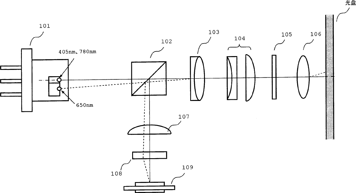
[0032] The configuration of an optical pickup device is shown in FIG. 1 . In addition, this optical pickup device is used as a CD / DVD / next-generation DVD compatible pickup.
[0033] As shown in the figure, the optical pick-up device is equipped with: 3-wavelength laser 101, polarized light BS (beam splitter) 102, collimator lens 103, beam expander 104, λ / 4 plate 105, objective lens 106, cylindrical lens 107, Optical axis correction element 108, and photodetector 109.
[0034] The 3-wavelength laser 101 houses three laser elements that respectively emit laser light for CD (infrared color: wavelength 780nm), laser light for DVD (red: wavelength 650nm), and laser light for next-generation DVD (blue 405nm). within the same CAN. The planes of polarization of laser light emitted from the respective laser elements are parallel to each other. In addition, the optical system from the polarized light BS102 to the objective lens 106, the cylindrical lens 107, the optical axis correcti...
Embodiment 2
[0069] FIG. 6 shows the configuration of the optical pickup device of this embodiment. In this embodiment, the optical axis of the DVD laser beam is aligned with the optical axis of the next-generation DVD laser beam before incident on the optical disk. In this embodiment, compared with the optical system of the first embodiment shown in FIG. 1 , the optical axis correction element 108 is omitted, and the optical correction element 110 is newly arranged. Other configurations are the same as those of the optical system of the first embodiment described above.
[0070] The DVD laser light (wavelength: 650 nm) emitted from the three-wavelength laser 101 is aligned on the optical axis of the next-generation DVD laser light (wavelength: 405 nm) by the optical correction element 110 , and then enters the polarized light BS 102 . Therefore, the laser light for DVD is incident on the optical system without deviation of the optical axis.
[0071] According to this embodiment, compare...
Embodiment 3
[0073]FIG. 7 shows the configuration of the optical pickup device of this embodiment. In this embodiment, the optical axis of the DVD laser is matched on the optical axis of the next-generation DVD laser, and the optical axis of the CD laser is matched on the optical axis of the next DVD laser. Compared to the optical system of the illustrated embodiment, the parallel plate 111 is reconfigured. Other configurations are the same as those of the optical system of the first embodiment described above.
[0074] FIG. 8 shows the relationship between the arrangement of the parallel plates and the correction action for optical axis misalignment.
[0075] When the thickness of the parallel plate is set as t, the inclination to the optical axis is set as a, and the refractive index is set as n, according to the offset h of the optical axis of the parallel plate, h=t / cos(sin -1 (sin(a) / n)*sin(a) to represent. Therefore, as shown in FIG. 8, as the forming material of the parallel plat...
PUM
| Property | Measurement | Unit |
|---|---|---|
| wavelength | aaaaa | aaaaa |
| wavelength | aaaaa | aaaaa |
| wavelength | aaaaa | aaaaa |
Abstract
Description
Claims
Application Information
 - R&D
- Intellectual Property
- Life Sciences
- Materials
- Tech Scout
- Unparalleled Data Quality
- Higher Quality Content
- 60% Fewer Hallucinations
Browse by: Latest US Patents, China's latest patents, Technical Efficacy Thesaurus, Application Domain, Technology Topic, Popular Technical Reports.
© 2025 PatSnap. All rights reserved.Legal|Privacy policy|Modern Slavery Act Transparency Statement|Sitemap|About US| Contact US: help@patsnap.com


