Fuel delivery pipe
A fuel delivery and fuel technology, which is applied in low-pressure fuel injection, fuel injection devices, liquid fuel engines, etc., can solve the problems of strong pulsation propagation and high manufacturing costs, and achieve the goals of improving layout, reducing vibration and noise, and reducing manufacturing costs Effect
- Summary
- Abstract
- Description
- Claims
- Application Information
AI Technical Summary
Problems solved by technology
Method used
Image

Examples
Embodiment 1
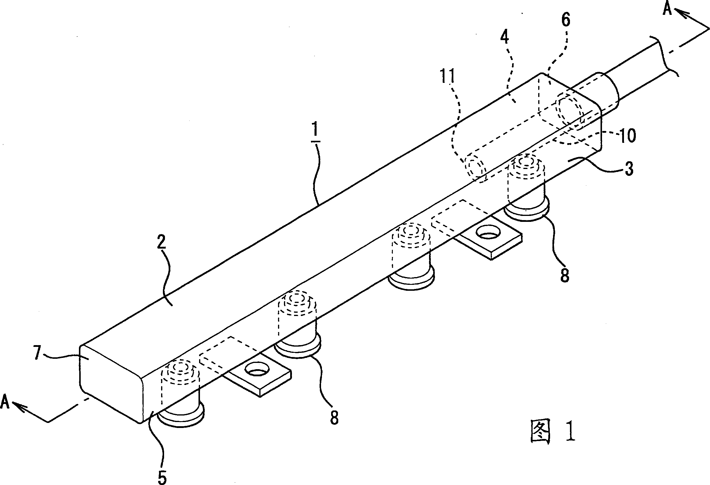
[0065] Referring to Fig. 1, Embodiment 1 of the fuel delivery pipe of the present invention is described in detail. Reference numeral 1 is the main body of the fuel delivery pipe, and its cross-sectional shape perpendicular to the direction of the pipe axis is a flat rectangular shape. And, the fuel delivery pipe main body 1 is constituted by the following parts: an upper wall 2 and a bottom wall 3 arranged in the pipe axis direction; a pair of side walls 4, 5 connecting the above-mentioned upper wall 2 and bottom wall 3; A pair of end walls 6, 7 configured at both ends. In addition, the total length of the upper wall 2 and the bottom wall 3 in the longitudinal direction is 320 mm, and the length in the width direction is 34 mm.
[0066] In addition, the height of the side walls 4 and 5 is 10.2 mm, and the plate thickness of the upper wall 2, the bottom wall 3 and the side walls 4 and 5 of the fuel delivery pipe main body 1 is 1.2 mm. In addition, a plurality of sleeves 8 are...
Embodiment 2
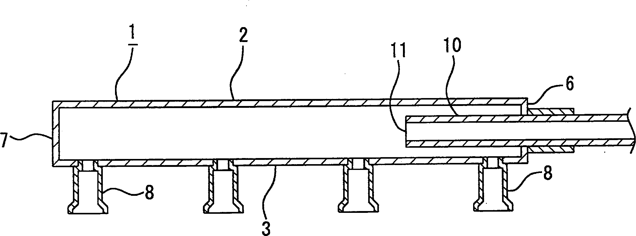
[0073] In addition, in the first embodiment described above, on the assumption that the overall length of the interior of the fuel delivery pipe main body 1 in the longitudinal direction is 100°, the fuel introduction pipe 10 is arranged so as to be inserted into the fuel delivery pipe main body 1 at a position where the length is 25°. , and connected to the main body of the fuel delivery pipe 1, while in embodiment 2, as Figure 5 As shown, the fuel inlet pipe 10 is configured to be inserted into the fuel delivery pipe main body 1 at a position of length 75 .
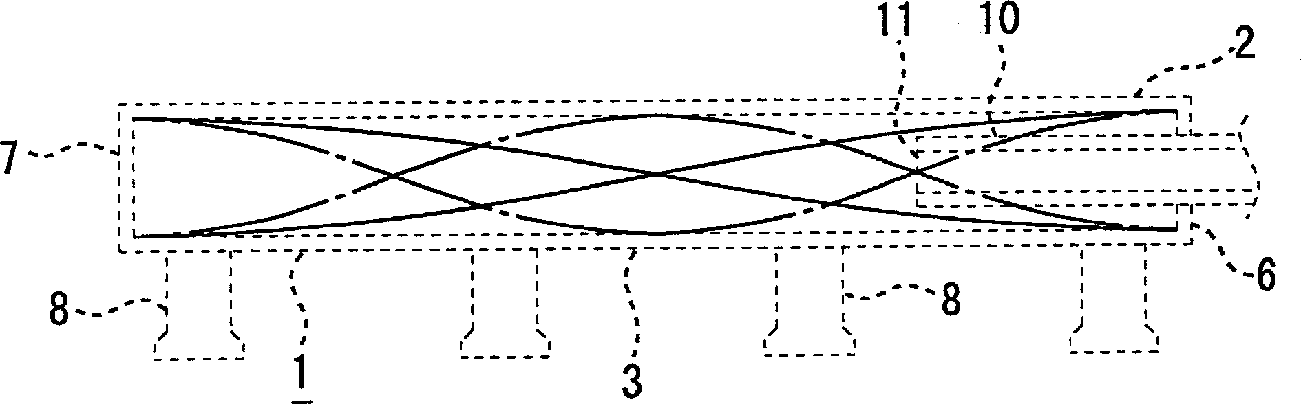
[0074] By inserting the fuel introduction pipe 10 into the inside of the fuel delivery pipe main body 1 at a position as long as the above, as Image 6 As shown, the opening 11 of the fuel introduction pipe 10 is disposed near the middle of the antinode and the node of the standing wave primary mode, and is also disposed at the node of the standing wave secondary mode generated inside the fuel delivery pipe main body 1...
Embodiment 3
[0076] In addition, in the above-mentioned Embodiments 1 and 2, assuming that the total length of the interior of the fuel delivery pipe main body 1 in the longitudinal direction is 100, the fuel introduction pipe 10 is arranged to be inserted into the interior of the fuel delivery pipe main body 1 by 25 and 75 lengths respectively. position and connected to the main body of the fuel delivery pipe 1, and in embodiment 3, as Figure 7 As shown, the fuel inlet pipe 10 is configured to be inserted into the fuel delivery pipe main body 1 at a position with a length of 33 .
[0077] By arranging the fuel introduction pipe 10 to be inserted into the interior of the fuel delivery pipe main body 1 at the length position as described above, as Figure 8 As shown, since the opening 11 of the fuel inlet pipe 10 is far away from the antinode of the standing wave primary mode, it is also far away from the antinode of the standing wave secondary mode, so it can comprehensively suppress the ...
PUM
 Abstract
Description
Claims
Application Information
 - R&D
- Intellectual Property
- Life Sciences
- Materials
- Tech Scout
- Unparalleled Data Quality
- Higher Quality Content
- 60% Fewer Hallucinations
Browse by: Latest US Patents, China's latest patents, Technical Efficacy Thesaurus, Application Domain, Technology Topic, Popular Technical Reports.
© 2025 PatSnap. All rights reserved.Legal|Privacy policy|Modern Slavery Act Transparency Statement|Sitemap|About US| Contact US: help@patsnap.com