Method and apparatus for modulating digital signal and recording medium
A technology of digital signal and modulation method, which is applied in the direction of digital recording/reproduction, data recording, recording signal processing, etc., and can solve the problems that digital modulation methods cannot be used
- Summary
- Abstract
- Description
- Claims
- Application Information
AI Technical Summary
Problems solved by technology
Method used
Image

Examples
no. 2 example
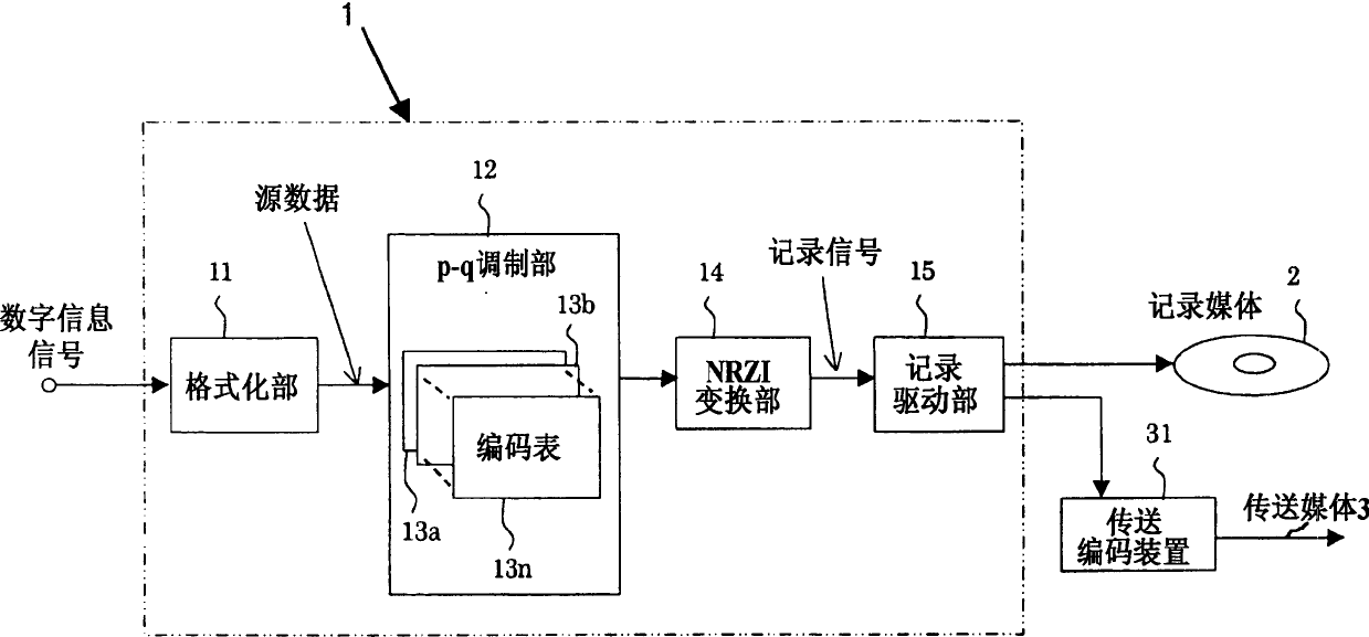
[0166] The second embodiment of the present invention will be described below together with the accompanying drawings. In FIG. 20, the same parts as those in FIG. 1 are assigned the same reference numerals. Fig. 20 is a schematic configuration diagram showing an example of a digital signal modulation method and a digital signal recording device equipped with a digital signal modulation device according to the present invention. In this figure, a digital signal recording device 1R includes: a digital signal modulator 10 composed of a formatting unit 11, a p-q modulating unit 22, encoding tables 231, 232, . . . 23n, and an NRZI (Non Return to Zero Inverse) converting unit 14. and the recording drive unit 15 . The input digital information signal is modulated by the digital signal modulator 10 to become a digital modulated signal, and is recorded on the recording medium 2 such as an optical disk by the recording drive unit 15 at high density.
[0167] Next, the operation of the...
no. 3 example
[0230] In FIG. 19 , the same reference numerals are used for the same components as those in FIG. 10 , and description thereof will be omitted. In FIG. 19, the digitally modulated signal taken out from the digital signal modulator 10 is supplied to the transmission coding unit 310, where the second digital modulation is performed as necessary so as to become a signal suitable for transmission via the network. signal, a header for transmission is added, and packet data with the header added is output. This packet data is transmitted to the other party's receiving device via a network not shown.
[0231] Fig. 20 shows a block diagram of an example of the above receiving apparatus. The receiving device 5 has a transmission decoding part 51 and a digital signal demodulator 52, and the packet data received by the receiving part not shown in the receiving device 5 is provided to the transmission decoding part 51 via the network, the header is removed, and then provided to the digit...
no. 4 example
[0238] An embodiment of the present invention will be described below together with the accompanying drawings. FIG. 21 is a block diagram of an embodiment of an encoding device of the present invention, and FIG. 22 is a block diagram of an embodiment of a main part of the encoding device of the present invention. First, an encoding device 1E according to an embodiment of the present invention will be described using FIG. 21 . Convert the image, sound, etc. to be coded into a binary sequence with a discretization device not shown in the figure, and the digital information signal thus obtained is matched with the recording format of the recording medium 2 in the formatting unit 11 for error correction. The so-called formatting such as addition of codes and sector structuring becomes a 4-bit source code sequence, which is then supplied to the 4-6 modulator 32 .
[0239] As will be described later, in order to encode the input source code, the 4-6 modulation unit 32 uses, for exa...
PUM
 Abstract
Description
Claims
Application Information
 - R&D
- Intellectual Property
- Life Sciences
- Materials
- Tech Scout
- Unparalleled Data Quality
- Higher Quality Content
- 60% Fewer Hallucinations
Browse by: Latest US Patents, China's latest patents, Technical Efficacy Thesaurus, Application Domain, Technology Topic, Popular Technical Reports.
© 2025 PatSnap. All rights reserved.Legal|Privacy policy|Modern Slavery Act Transparency Statement|Sitemap|About US| Contact US: help@patsnap.com