
Arc welding control method and arc welding device

A control method and technology for arc welding machines, applied in arc welding equipment, manufacturing tools, welding equipment, etc., can solve the problems of reducing welding operation efficiency, deteriorating price-performance ratio, etc., and achieve the effect of reducing welding voltage and expanding application scope.

Active Publication Date: 2006-08-16
PANASONIC CORP
View PDF2 Cites 14 Cited by
  • Summary
  • Abstract
  • Description
  • Claims
  • Application Information

AI Technical Summary

Problems solved by technology

If such corrections are not possible, weldments with such welded parts must be discarded, which reduces the efficiency of the welding operation and greatly deteriorates the price-performance ratio

Method used


Image

  • Arc welding control method and arc welding device
  • Arc welding control method and arc welding device
  • Arc welding control method and arc welding device

Examples


Embodiment 1

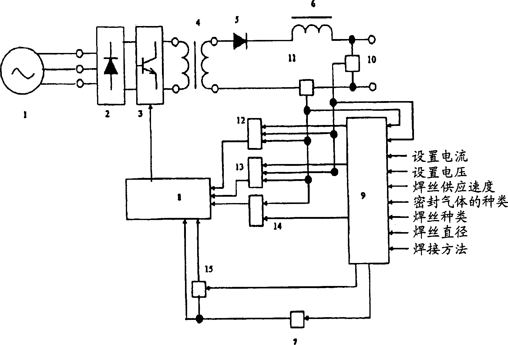
[0036] exist figure 1 Among them, the reference number 1 represents the mains AC power supply, which is used to input the AC current; 2 represents the primary rectification part, which is used to rectify the input current input from the mains power supply; 3 represents the switch element weldment, which is used to control Welding output; 4 represents the transformer, which is used to transform the voltage while isolating the power supply; 5 represents the secondary rectification part, which is used to rectify the secondary output of the transformer; 6 represents the reactance coil (DCL); 7 represents the short circuit arc determination part, It is used to determine whether the welding state is in the short-circuit period or the arc period; 8 indicates the driving part; 9 indicates the setting part, which is used to set various parameters according to the setting bar weldment, the setting bar weldment includes the set current, the set Voltage, supply of electrode, type of seal...


PUM


Abstract

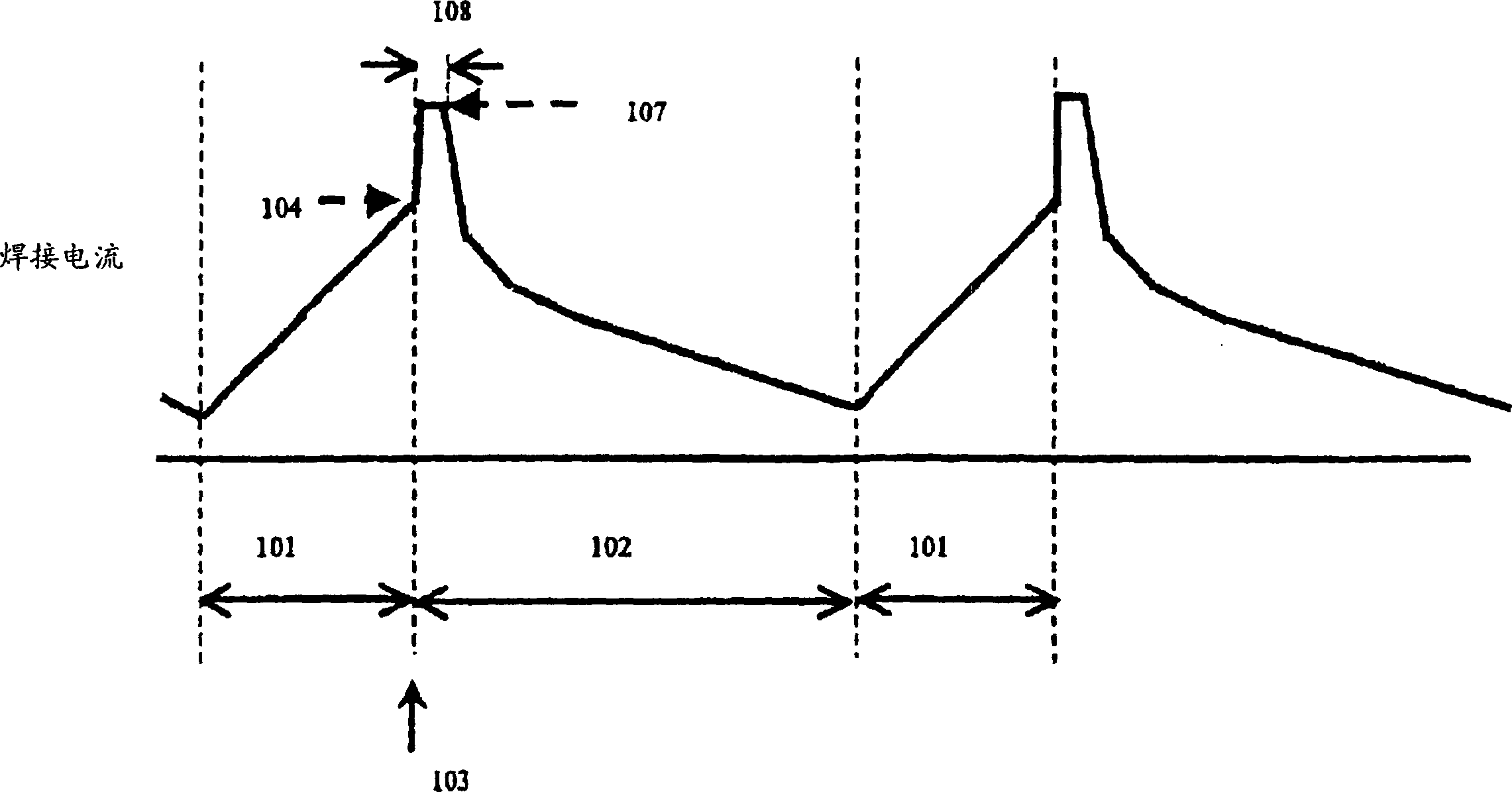
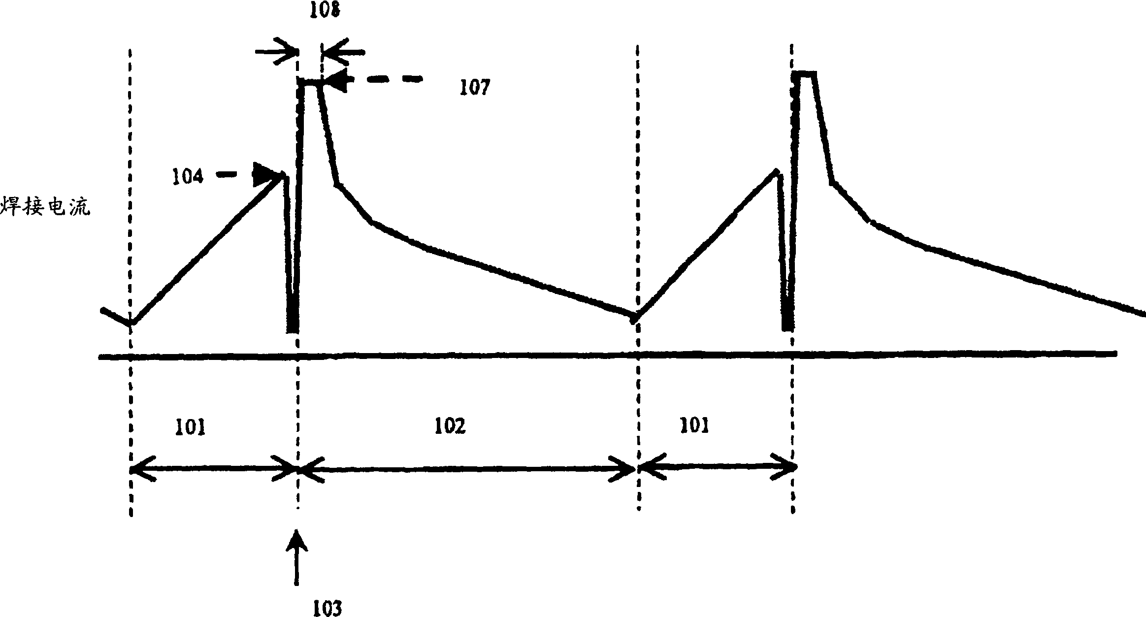
An arc welding control method performs welding of a work by alternately repeating a short-circuit period for short-circuiting a welding wire to a work and an arc period for regenerating an arc to perform arc discharge. The control is performed so that the welding output current immediately after regeneration of the arc is maintained higher than the welding output current immediately before the arc regeneration for a predetermined period of time.

Description

technical field [0001] The present invention relates to a consumable electrode type arc welding machine and an arc welding control method which generate an arc between an electrode composed of a consumable electrode and a base metal or weldment to be welded, thereby welding the base metal and control welding output. Background technique [0002] In an arc welder, when the generation of sputtering increases, vaporized metal adheres to the base metal, deteriorating welding quality. Also, when sputtering is generated beyond an allowable frequency, it is necessary to correct the operation of the welded portion. If such correction is impossible, weldments having such welded portions must be discarded, which reduces the efficiency of the welding operation and greatly deteriorates the price-performance ratio. [0003] Conventionally, various methods have been proposed in which sputtering is reduced to thereby reduce the number of steps for correcting welded portions. For example...

Claims


Application Information

Patent Timeline
Patent Type & Authority Applications(China)
IPC IPC(8): B23K9/073B23K9/095
CPCB23K9/0732B23K9/073B23K9/09B23K9/095
Inventor 川本笃宽向井康士相见圭古和将
Owner PANASONIC CORP
Learn More