
Chip-style radiating module and radiating method thereof

A technology of heat dissipation module and heat dissipation method, which is applied in the direction of electrical components, electric solid devices, circuits, etc., and can solve problems such as easy condensation, interference, and discounted heat dissipation effect

Inactive Publication Date: 2006-08-16
MACS TECH
View PDF1 Cites 4 Cited by
  • Summary
  • Abstract
  • Description
  • Claims
  • Application Information

AI Technical Summary

Problems solved by technology

[0003] The known heat dissipation system is mainly a passive heat dissipation system, which uses a metal or metal alloy with good heat conduction as a heat conductor, and increases the heat conductor and fluids such as air or water by arranging fins or holes on the heat conductor. In order to improve the effect of heat convection, this kind of passive heat dissipation system makes various changes in the number, position, angle, and direction of convection flow of heat dissipation fins, in order to obtain better heat dissipation effect , or try various alloy ratios and composite material ratios on the material of the conductor in order to obtain better heat conduction. However, because the heat transfer methods include convection, conduction and radiation, inside the central microprocessor, These three heat transfer methods will interfere with each other, thus reducing the cooling effect
[0004] In addition, there is also a thermoelectric cooler (Thermal Electric Cooler) in contact with the heating central microprocessor, through the characteristics of the heat-absorbing surface and the heating surface on both sides of the semiconductor chip due to the current conduction effect of the thermoelectric cooler, the heat-absorbing The surface is in contact with the heating central microprocessor, and the heating surface is in contact with heat sinks, cooling fans, etc., to achieve the effect of cooling the temperature of the central microprocessor (as disclosed in Taiwan Patent No. 088203663), In this structure and method, the thermoelectric cooler must be connected with a voltage and current to cause a temperature difference between the two sides of the semiconductor wafer to achieve the effect of absorbing heat on one side and generating heat on the other side. However, due to the characteristic of temperature difference Therefore, when the heat dissipation element on the heating surface is insufficient in heat dissipation, the temperature of the heat-absorbing surface will be affected, and the heat energy will flow back to the heat-absorbing surface. In addition, due to the rapid temperature rise and fall, condensation is easy to occur, which also makes the thermoelectric cooler used in the center Considerable room for improvement in microprocessor cooling

Method used


Image

  • Chip-style radiating module and radiating method thereof
  • Chip-style radiating module and radiating method thereof
  • Chip-style radiating module and radiating method thereof

Examples


Embodiment approach

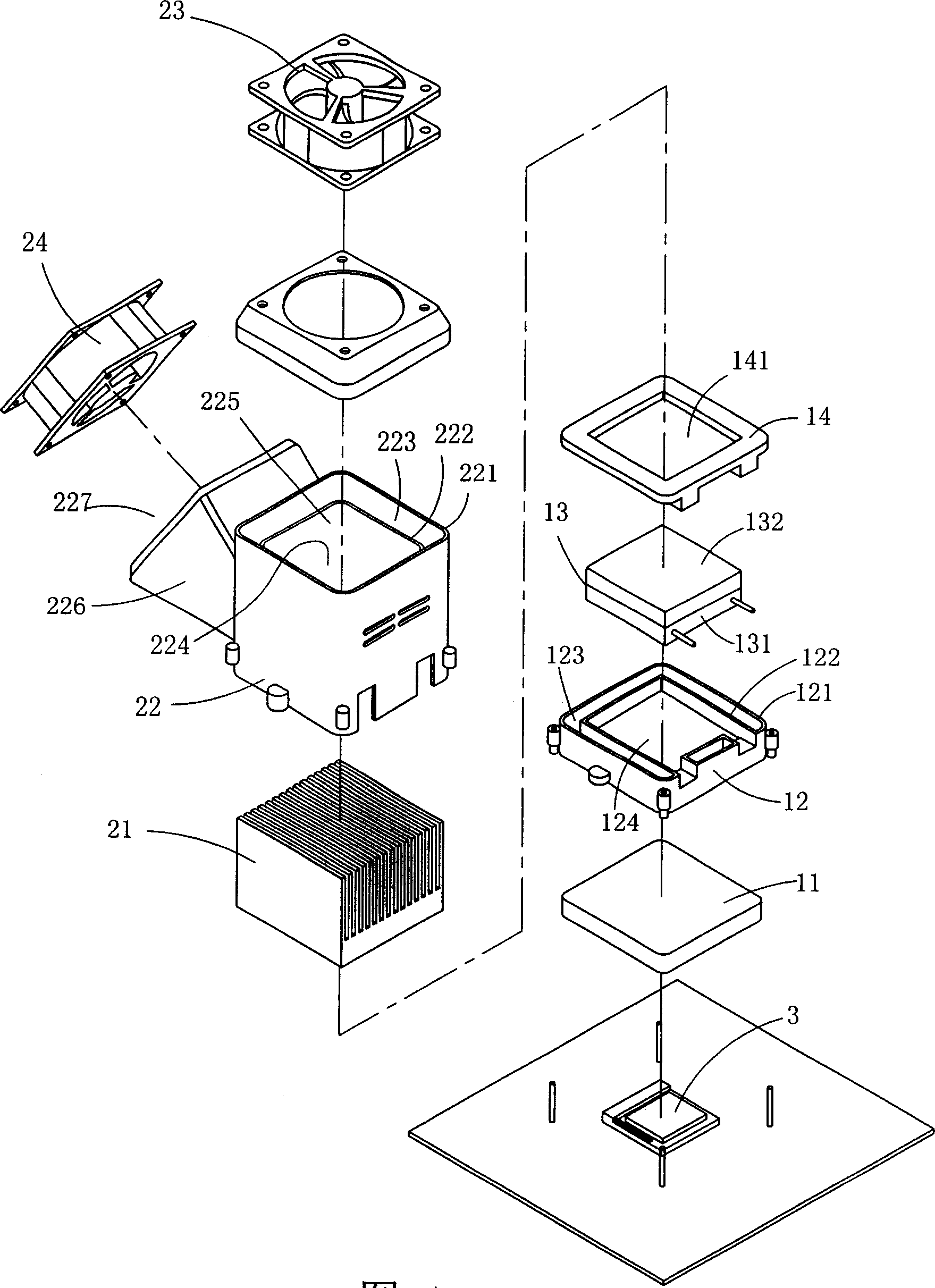
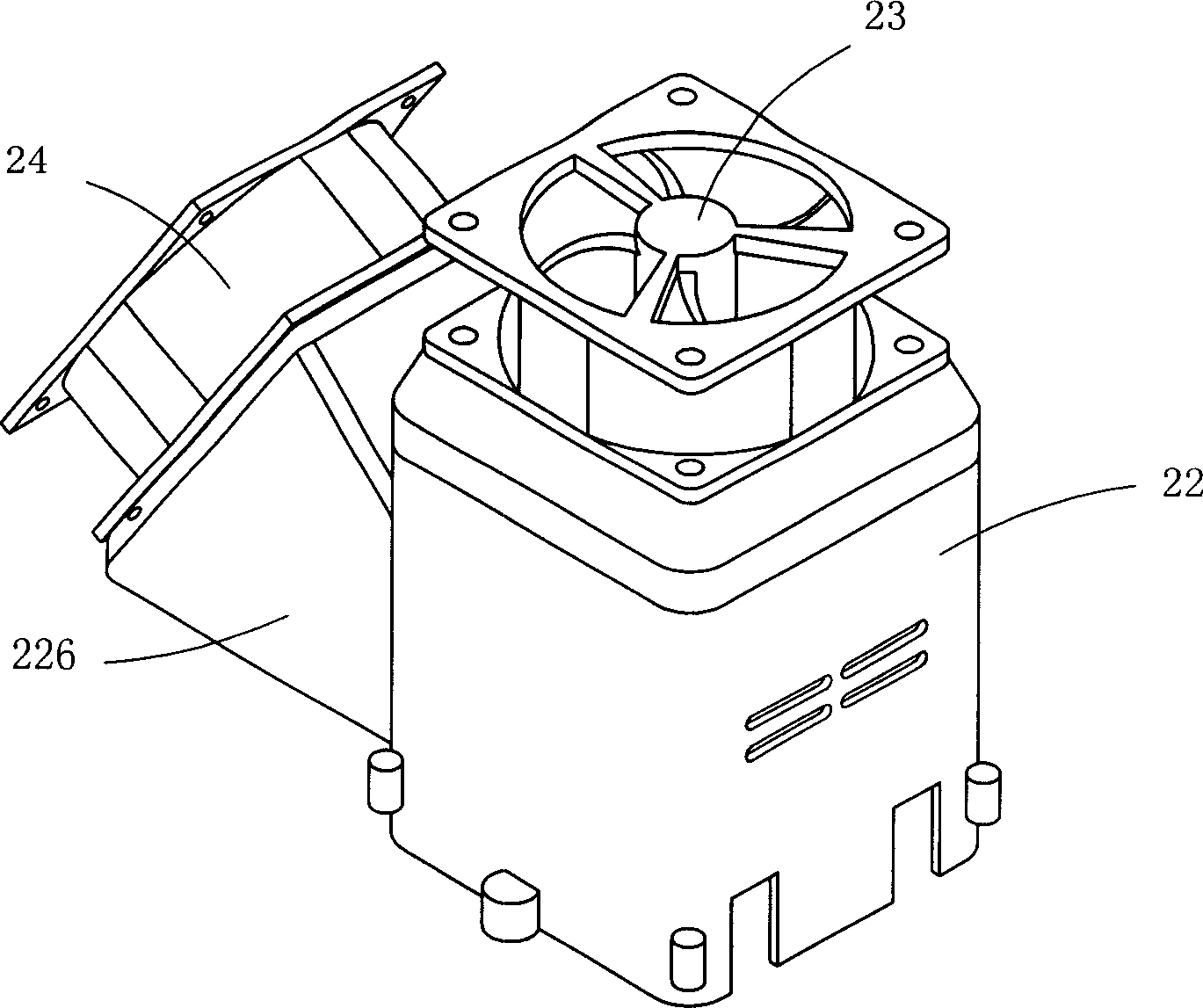
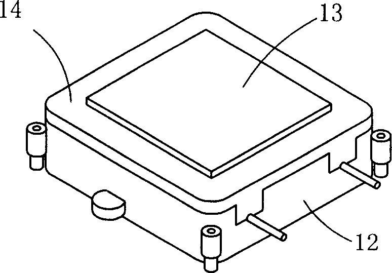
[0017] see Figure 1 to Figure 4 , is a perspective view of a preferred embodiment of the chip cooling module of the present invention, the chip cooling module in the embodiment is used to dissipate the heat generated by a central microprocessor 3 (CPU).

[0018] The wafer heat dissipation module in this embodiment mainly includes a metal cover plate 11, a first casing 12, a thermoelectric cooler 13 (Thermal electric cooler), a heat dissipation fin 21, a second shell 22, a first A fan 23 and a second fan 24 are formed.

[0019] In order to allow most of the heat source produced by the central microprocessor 3 to conduct to the thermoelectric cooler 13, the metal cover 11 covers the central microprocessor 3 and is in contact with the central microprocessor 3 and the thermoelectric cooler 13. The metal cover plate 11 has the function of concentrating the heat generated by the central microprocessor 3. The first housing 12 is composed of inner and outer two-layer shell walls 121...


PUM


Abstract

The invention is for use in cooling CPU in operation. It includes a metal cover plate, a first case, a thermoelectric cooler, a heat sink, a second case, a first fan and a second fan. With the metal cover plate the heat source from CPU is isolated, and then the thermoelectric cooler reduces temperature of CPU and conducts the heat to the heat sink. The first and second fans vent the heat out. The working power of thermoelectric cooler and switch of first and second fans are controlled by application software.

Description

【Technical field】 [0001] The present invention relates to a chip type heat dissipation module and a heat dissipation method thereof, in particular to a heat dissipation module with a chip type thermoelectric cooler (Thermal electric cooler) and a heat dissipation method thereof. 【Background technique】 [0002] The more advanced the technology, the faster and faster the calculation speed and the more and more data processing capacity will be in the evolution of the components inside the electronic products, but correspondingly, the central microprocessor will also generate more and more heat energy, which affects the The work efficiency and quality of the central microprocessor, so heat dissipation has always been a topic that cannot be ignored in the process of research and development of electronic products. The competition of modern science and technology in heat dissipation products can not be called a hundred schools of thought. [0003] The known heat dissipation system...

Claims


Application Information

Patent Timeline
IPC IPC(8): H01L23/34
Inventor 郭慰珍
Owner MACS TECH
Learn More