Hard coating, target for forming hard coating, and method for forming hard coating
A technology of hard coating and film-forming gas, which is applied in the direction of coating, metal material coating process, ion implantation plating, etc., to achieve excellent hardness and lubricity, and prolong service life
- Summary
- Abstract
- Description
- Claims
- Application Information
AI Technical Summary
Problems solved by technology
Method used
Image
Examples
Embodiment
[0127] The following methods were used to evaluate the physical properties of the hard coatings obtained in the following experimental examples:
[0128] [Composition of Hard Coat]
[0129] Composition was determined using EPMA. In this method, it was also confirmed that the content of impurities other than metal elements and nitrogen, the content of oxygen and the content of carbon did not exceed 5 atomic %, respectively.
[0130] [Conditions used in crystal structure analysis]
[0131] The crystal structure of the hard coat layer was evaluated by performing X-ray diffraction by the θ-2θ method using an X-ray diffractometer manufactured by Rigaku Electric. X-ray diffraction of cubic crystals was performed using a CuKα source, and the peaks of the (111) surface, (200) surface, and (220) surface were measured at about 2θ = 37.78°, about 2θ = 43.9°, and about 2θ = 63.8°, respectively strength. X-ray diffraction of hexagonal crystals was performed using a CuKα source, and the...
experiment Embodiment 1
[0169] [Formation of hard coat layer]
[0170] The target 6 used was a target having a composition shown in Table 1 "Composition Ratio (Atomic Ratio) of Target".
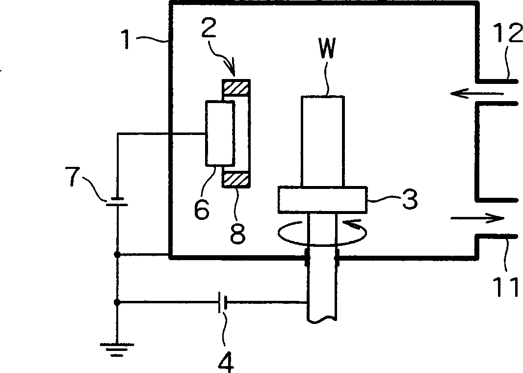
[0171] Chamber 1 was evacuated, and the object was heated to 500°C with a heater (not shown). A single gas or a mixed gas having a composition of "composition ratio (atomic ratio) of film-forming gas" shown in Table 1 was supplied from gas inlet 12 into chamber 1 until the pressure of chamber 1 reached 2.66 Pa. A voltage of 20 to 100V is applied to the target from the bias power supply 4, so that the target W is a negative voltage relative to the ground voltage. Arc discharge was then started by the arc power source 7 to evaporate and ionize the target 6 to deposit a 3 μm hard coat on the surface of the target piece W.
[0172] [Physical Properties of Hard Coat]
[0173] Crystal structure, value of formula (1), hardness, coefficient of friction and wear width were evaluated for the obtained hard coating layer. T...
experiment Embodiment 2
[0178] [Formation of hard coat layer]
[0179] The experiment was performed by repeating the procedure of Experimental Example 1, except that the target 6 used was a target having a composition shown in Table 2 as "composition ratio (atomic ratio) of target".
[0180] [Physical Properties of Hard Coat]
[0181]The crystal structure, value of formula (1), hardness, coefficient of friction, and wear width of the obtained hard coating layer were evaluated. The results are shown in Table 2.
[0182] Target composition ratio
[0183] Compared with conventional coatings comprising TiAlN (Comparative Example 1) and CrAlN (Comparative Example 2), the hard coatings of the present invention (Examples 15 to 33) all have better hardness, lower coefficient of friction and narrower wear width. Hardcoats that also contained Si and B (Examples 16 to 33) had equal or better properties than the inventive hardcoats that did not contain Si or B (Example 15). However, coatings outs...
PUM
| Property | Measurement | Unit |
|---|---|---|
| thickness | aaaaa | aaaaa |
| melting point | aaaaa | aaaaa |
| magnetic flux density | aaaaa | aaaaa |
Abstract
Description
Claims
Application Information
 - R&D
- Intellectual Property
- Life Sciences
- Materials
- Tech Scout
- Unparalleled Data Quality
- Higher Quality Content
- 60% Fewer Hallucinations
Browse by: Latest US Patents, China's latest patents, Technical Efficacy Thesaurus, Application Domain, Technology Topic, Popular Technical Reports.
© 2025 PatSnap. All rights reserved.Legal|Privacy policy|Modern Slavery Act Transparency Statement|Sitemap|About US| Contact US: help@patsnap.com


