High-performance mechanical particle spreader

A high-performance mechanical, particle technology, applied in aircraft indicating devices, aircraft parts, transportation and packaging, etc., can solve problems such as the influence of current changes and stability, and achieve the effect of ensuring uniformity

Inactive Publication Date: 2006-08-16
HARBIN INST OF TECH
View PDF0 Cites 3 Cited by
  • Summary
  • Abstract
  • Description
  • Claims
  • Application Information

AI Technical Summary

Problems solved by technology

This method is very sensitive to the resonance generated by vibration and the weight change of the device. The weak current change in the oscillator, the fluctuation of the jet pressure, and the inevitable change in the weight of the device as the particles are broadcast will affect its stability.

Method used


Image

  • High-performance mechanical particle spreader
  • High-performance mechanical particle spreader
  • High-performance mechanical particle spreader

Examples


Embodiment Construction

[0019] The present invention is described in detail below in conjunction with accompanying drawing example:

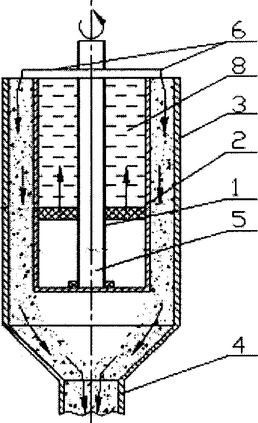
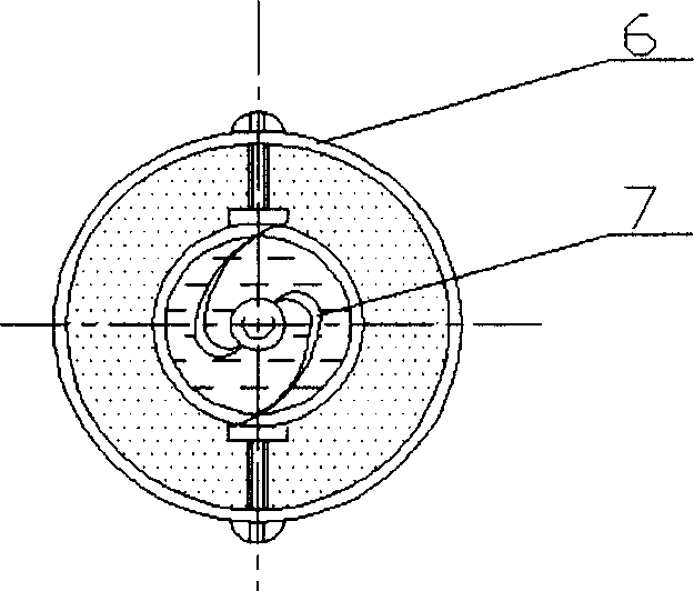
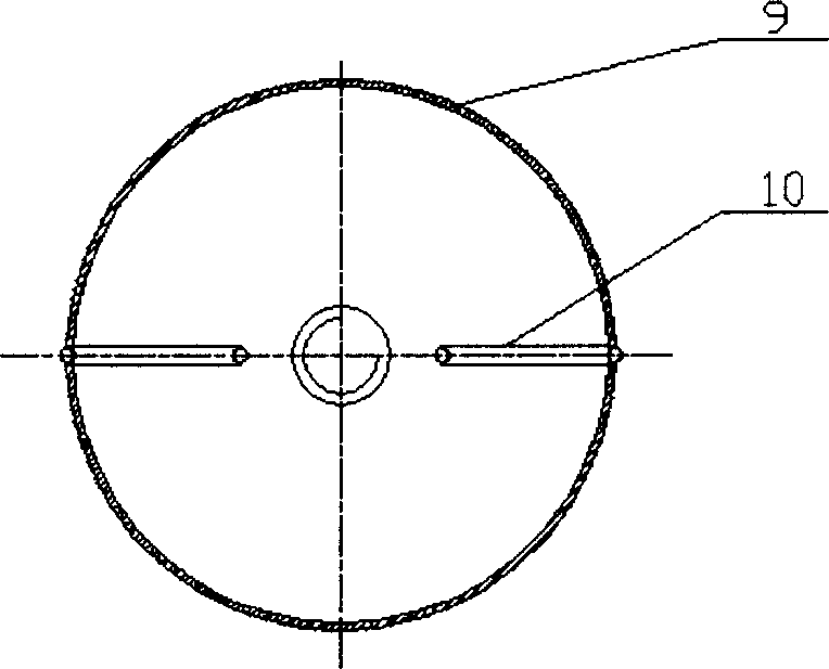
[0020] combine figure 1 , the composition of the high-performance mechanical particle broadcasting device includes a cylindrical silo 1, a container 3 is arranged outside the cylindrical silo, a screw 5 is arranged in the middle of the cylindrical silo, and the bottom of the screw passes through the bearing and the cylinder The bottom surface of the shaped silo is connected, the screw is provided with a base 2 through threads, and a screw discharge device is installed at the outlet of the cylindrical silo of the screw. combine image 3 , A rubber ring 9 is set between the base and the cylindrical silo; a guide wire 10 is set between the base and the cylindrical silo. combine figure 2 , the screw discharge device is a blade 6 installed on the screw rod.

[0021] (1) The bottom of the screw rod 5 is connected to the bottom of the cylindrical silo 1 through a bearing...


PUM


Abstract

A high-performance mechanical particle distributor for uniformly distributing the particles into high-temp heat flow generated by the spray tube of arc heater at a certain mass flow rate is composed of cylindrical material cabin, container outside said cylindrical cabin, central screw bolt in said cylindrical cabin and linked with its bottom via bearing, and a spiral discharging unit at the outlet of cabin.

Description

(1) Technical field [0001] The invention relates to a mechanical particle distributing device for uniformly distributing particles into the high-temperature heat flow provided by an arc heater nozzle at a certain mass flow rate. (2) Background technology [0002] When a reentry vehicle enters the atmosphere, it will face harsh environmental challenges. The aerodynamic heating caused by the high-speed incoming flow will cause the temperature of the aircraft head to rise suddenly and cause the material to ablate and retreat. On the other hand, when the aircraft re-enters the atmosphere, it will also encounter particle clouds produced by nature or man-made. Particle cloud components include water vapor condensate particles such as water droplets, ice crystals, and snowflakes, and dust suspended in the atmosphere. Since the reentry speed of the aircraft is very high, usually reaching tens of Machs, particle erosion will have a very serious impact on the retreat and shape stabil...

Claims


Application Information

Patent Timeline
Patent Type & Authority Applications(China)
IPC IPC(8): B64D45/00
Inventor 韩杰才孟松鹤张博明
Owner HARBIN INST OF TECH
Why Eureka
Try Eureka