
Flash module with quantum dot light conversion

A quantum dot and wavelength conversion technology, which is applied in optics, light source, nano-optics, etc., can solve the problems of great changes in light source luminous quality

Active Publication Date: 2006-08-02
EPISTAR CORP
View PDF1 Cites 23 Cited by
  • Summary
  • Abstract
  • Description
  • Claims
  • Application Information

AI Technical Summary

Problems solved by technology

[0004] However, light sources of the same color temperature can vary widely in light quality

Method used


Image

  • Flash module with quantum dot light conversion
  • Flash module with quantum dot light conversion
  • Flash module with quantum dot light conversion

Examples


Embodiment Construction

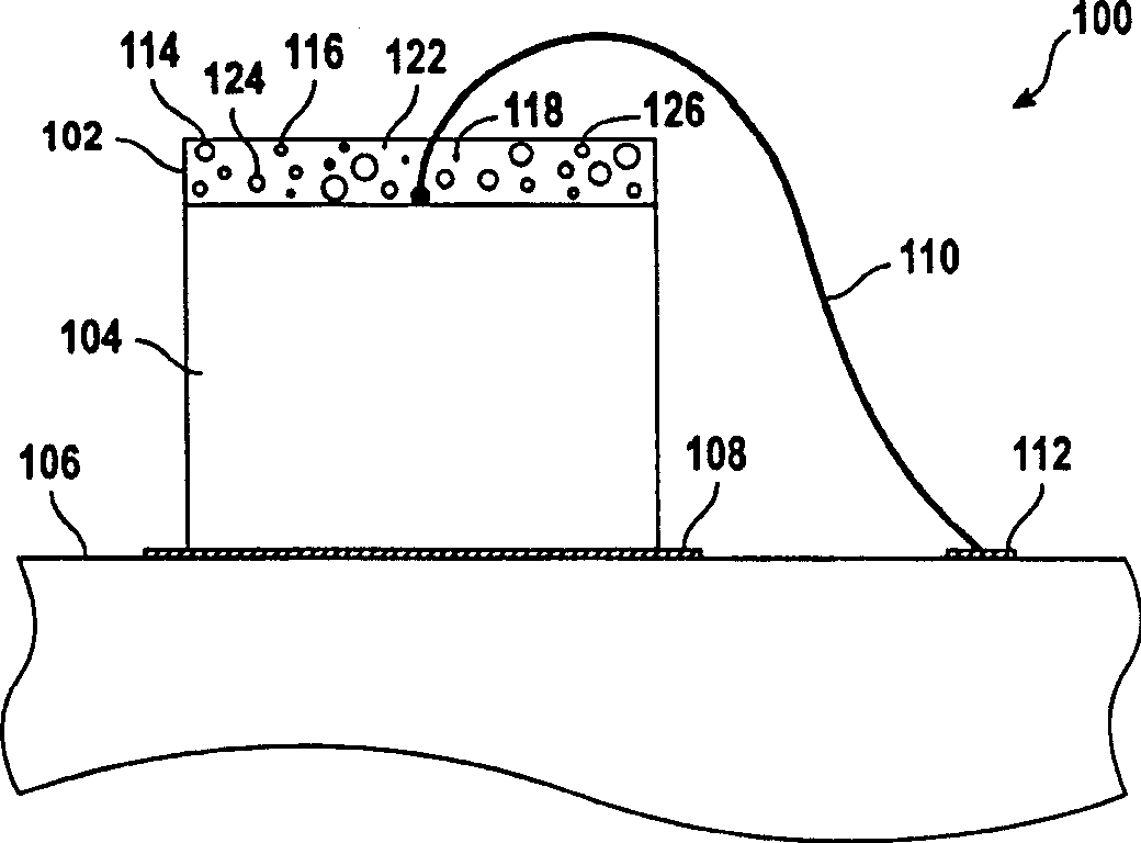
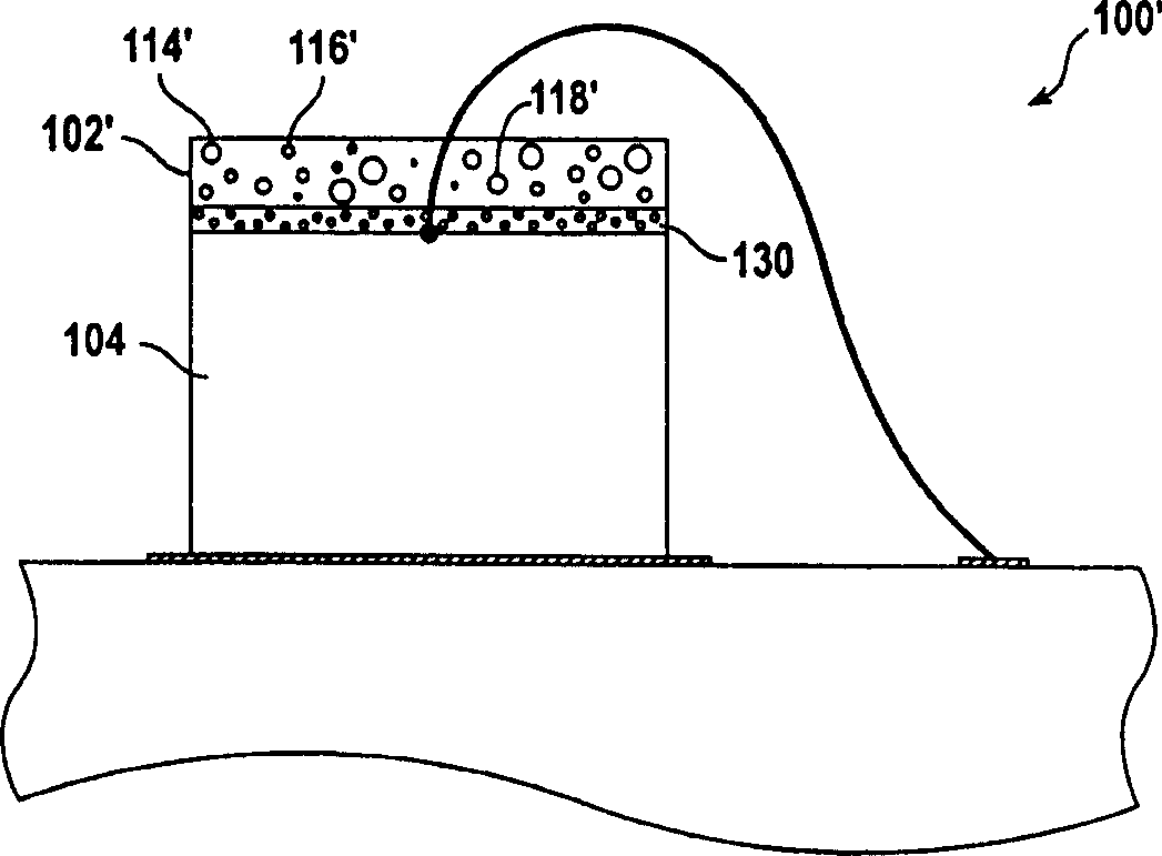
[0015] Figure 1A is a side view of a light emitting device 100 with a wavelength converting coating 102 used in an embodiment of the invention. The light emitting device includes a light source 104, such as an LED chip, mounted on a substrate 106, a carrier or a head. Alternatively, another type of light source such as a semiconductor vertical cavity surface emitting laser VCSEL is used. Light source 104 is soldered or otherwise attached (“die attached”) to first electrical contact pad 108 , and wire bonds 110 attach electrodes (not shown) of light source 104 to second electrical contact pad 112 . The electrical contact pads 108, 112 are connected to a current source, which in some embodiments is a variable current source.

[0016] Light source 104 includes LEDs (not shown) that emit a relatively narrow range of light. In certain embodiments, the LED is a blue LED with a center wavelength of less than 450 nm. In other embodiments, the LED has a center wavelength of less th...


PUM


Abstract

An LED chip (104), mounted on a substrate (106), emits a first primary light. A wavelength-converting overlay (102) is disposed on the LED chip, the overlay comprising quantum dots (114,116,118) dispersed in a matrix material (122). A second light source provides a second color of light.

Description

technical field [0001] The present invention relates to light emitting diode ("LED") devices, and more particularly, to LED devices that mix the light of multiple LEDs to produce white light. Background technique [0002] Light is the basis of imaging, and the properties of light affect the final image quality. For example, the color of the light source used for imaging can affect the tone of the image. The color temperature of a color and its color rendering index ("CRI") are often used to characterize the color of a light source. Color temperature is an index of the light provided by a light source compared to the light emitted by a black body radiator at a certain temperature. For example, a 100 watt incandescent lamp has a color temperature of approximately 2870 degrees Kelvin, which means that the light emitted by the incandescent lamp is approximately the same color as a black body heated to 2870 degrees Kelvin. [0003] Color temperature is useful for determining t...

Claims


Application Information

Patent Timeline
Patent Type & Authority Applications(China)
IPC IPC(8): H01L25/075H01L33/00F21K99/00G03B15/02H01L33/50
CPCB82Y10/00G03B15/05Y10S362/80H01L33/504H04N5/2256H01L33/502B82Y20/00H01L33/508H01L2224/48091H01L2224/48465H01L2224/8592G03B2215/0567H04N23/56H01L2924/00014H01L2924/00
Inventor 蔡美莺李健欣伍启元
Owner EPISTAR CORP
Learn More