
Master cylinder

A technology for cylinder body and inner diameter, which is applied in brakes, mechanical equipment, transportation and packaging, etc. It can solve the problems of increased processing cost and time spent in processing, and achieve the effects of shortening processing length, suppressing cost increase, and reducing air retention

Active Publication Date: 2006-07-26
HITACHI LTD
View PDF2 Cites 5 Cited by
  • Summary
  • Abstract
  • Description
  • Claims
  • Application Information

AI Technical Summary

Problems solved by technology

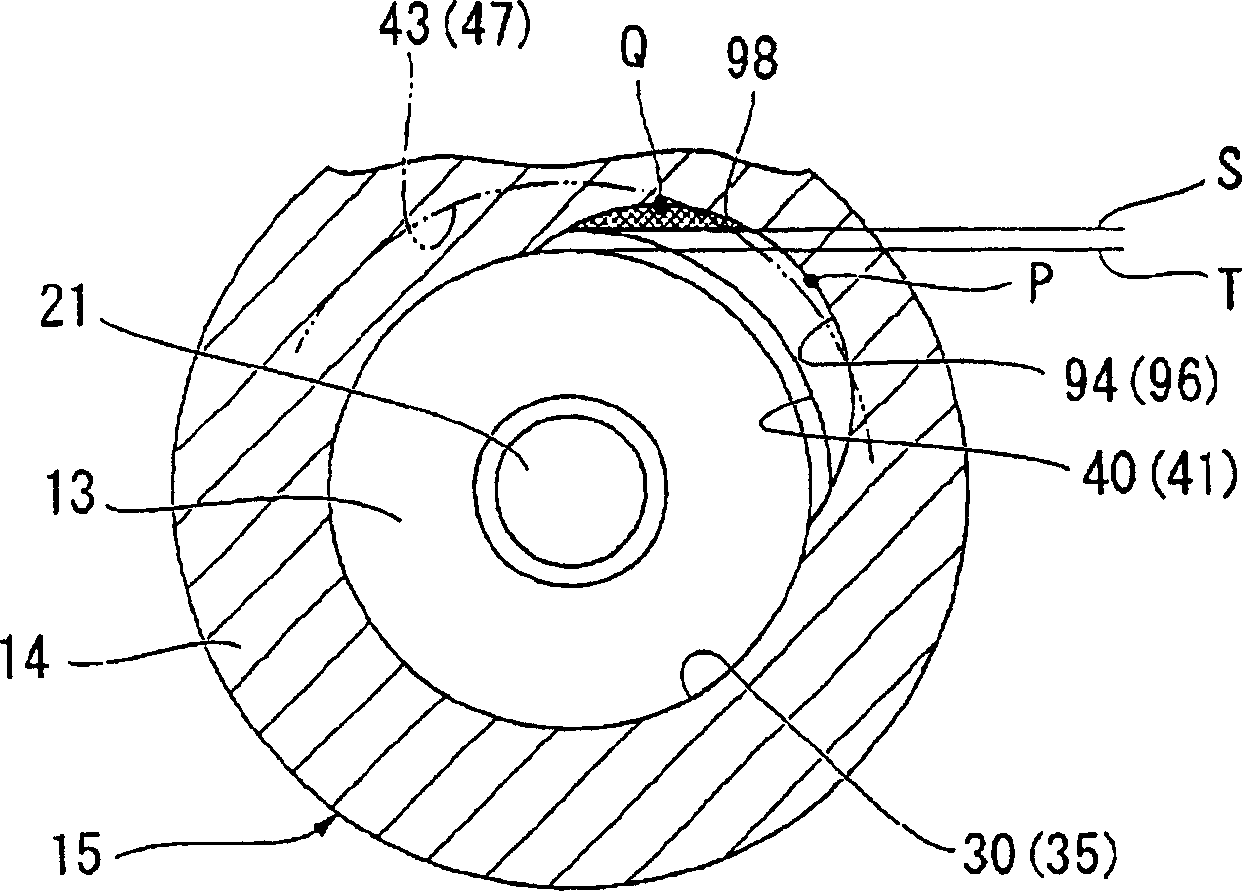
[0006] However, in the above-mentioned master cylinder, the arc center of the arc-shaped communication groove is eccentric with respect to the center of the sliding inner diameter part of the cylinder body, and since the processing length of the communication groove needs to be increased, it takes time for processing and increases the processing cost.

Method used


Image

  • Master cylinder
  • Master cylinder
  • Master cylinder

Examples


Embodiment Construction

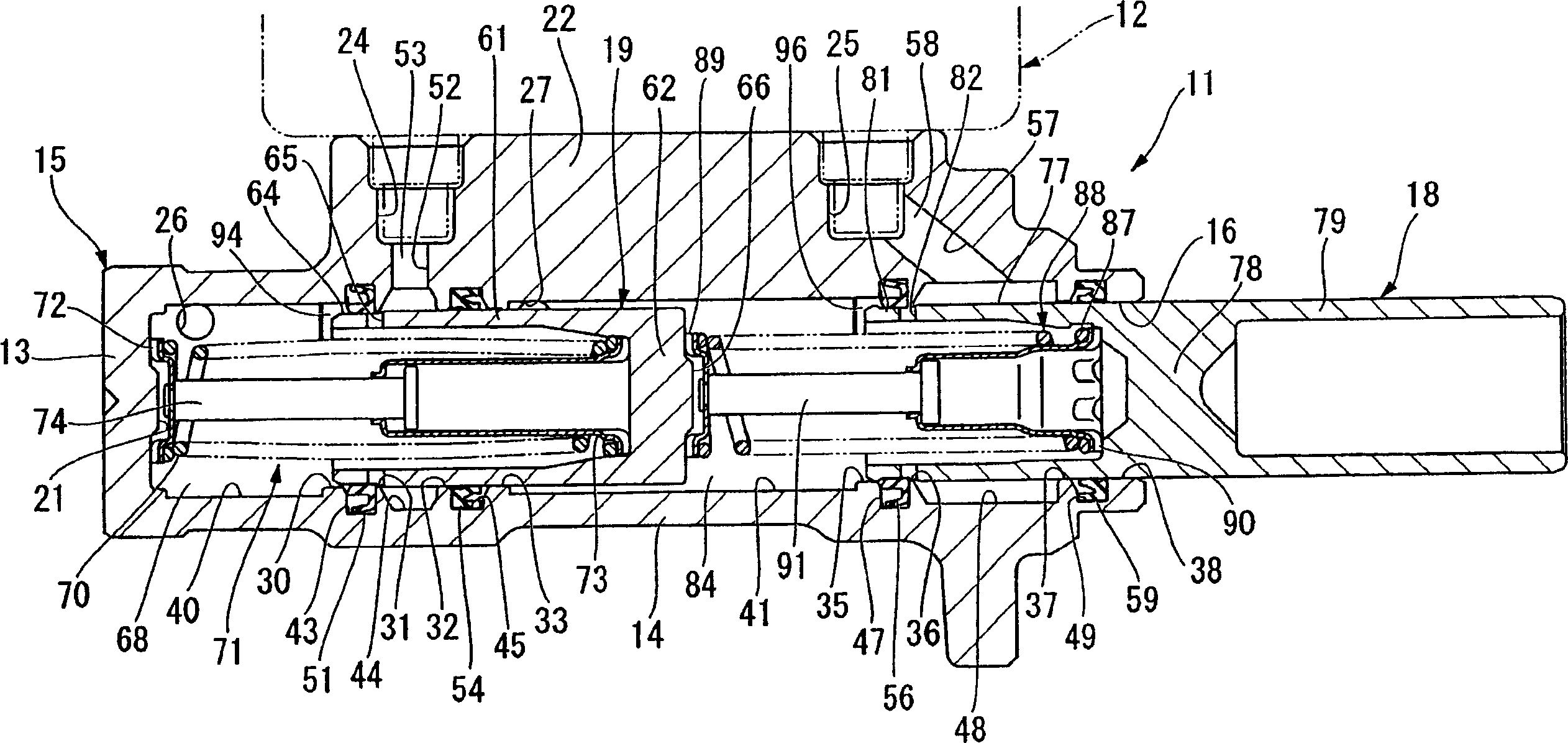
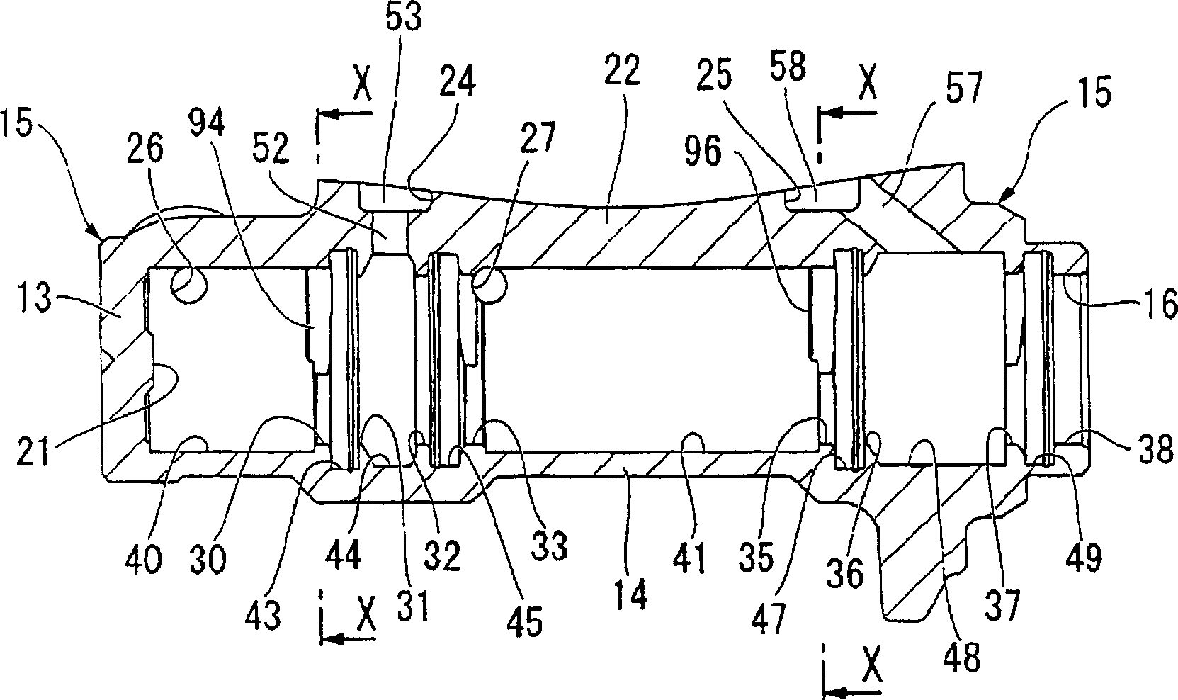
[0047] Refer to attached Figure 1~5 A master cylinder according to an embodiment of the present invention will be described.

[0048] figure 1 In the figure, reference numeral 11 denotes a master cylinder in this embodiment, which generates brake fluid pressure by a force corresponding to the operation amount of the brake pedal introduced through a brake booster not shown. An oil tank 12 for supplying and discharging brake fluid to the upper side of the master cylinder 11 is attached.

[0049] The master cylinder 11 is a tandem type cylinder having: a cylinder main body 15 having a bottom 13 and a cylindrical portion 14, processed into a bottomed cylindrical shape from one material, and disposed on the vehicle in a transverse posture; a primary piston (piston ) 18, which is slidably inserted into the opening 16 side of the cylinder main body 15 along the axis of the cylindrical portion 14 of the cylinder main body 15 (hereinafter referred to as the cylinder shaft) ( figure...


PUM


Abstract

Disclosed is a master cylinder, which has no limit to the brake fluid supply while the air is drawn out, and can restrain the increase of the cost of the connected groove processing, wherein, a pressure chamber part is formed in the cylinder body (15); big- diameter- hole parts (40, 41) with diameter bigger than sliding internal diameter parts (30, 35) are formed coaxially with the sliding internal diameter parts (30, 35) on the side opposite to circumferential grooves (43, 47) of the sliding internal diameter parts (30, 35); communicated grooves (94, 96) which are used for communicating the circumferential grooves (43, 47) with the big- diameter- hole parts (40, 41) are formed on the upper part of the sliding internal diameter parts (30, 35); the deepest position of the communicated grooves (94, 96) are closer to the radial outer side than the bottom of the circumferential grooves. Thereby, while the air is drawn out, the supply of the brake fluid is not limited, so as to reduce the length of the communicated grooves (94, 96), the processing period and the increase of the cost.

Description

technical field [0001] The present invention relates to a master cylinder for supplying brake fluid to a brake device of a vehicle. Background technique [0002] As a master cylinder for supplying brake fluid to a brake device of a vehicle, there is a structure in which a plunger-type piston is directly fitted and inserted into a cylinder body. In this kind of master cylinder, in order to connect the peripheral groove in which the piston oil seal is embedded with the discharge passage on the bottom side of the cylinder, an annular large-diameter groove is provided in the cylinder body on the discharge passage side, and the large-diameter groove is connected. The linear communication groove between the groove and the above-mentioned peripheral groove is provided in the upper part inside the cylinder main body. In addition, when the air in the cylinder main body is extracted, the piston oil seal is opened by the pressure difference, and the brake fluid is supplied to the pist...

Claims


Application Information

Patent Timeline
Patent Type & Authority Applications(China)
IPC IPC(8): B60T11/16
CPCF15B7/08B60T11/236
Inventor 毛利友纪甘利泰彦舆水长典
Owner HITACHI LTD
Learn More