
A sewage lifting system

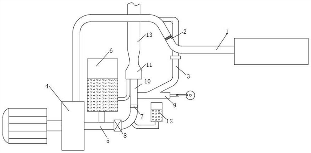
A sewage lifting and sewage pumping technology, applied in waterway systems, water supply devices, drainage structures, etc., can solve problems such as manual maintenance, reducing sewage pump lifting efficiency and lifting height, and filter blockage, so as to reduce flow resistance and energy consumption , reduce the frequency of manual participation, and reduce the effect of garbage accumulation

Active Publication Date: 2021-12-14
山西交控生态环境股份有限公司
View PDF0 Cites 0 Cited by
  • Summary
  • Abstract
  • Description
  • Claims
  • Application Information

AI Technical Summary

Problems solved by technology

However, because the composition of the sewage is too complex and contains a lot of large impurities, it is easy to cause the submersible pump to be blocked or damaged. Although most of the problems can be solved by adding a filter screen and a rotating cutting head, on the one hand, the long-term After use, there is a phenomenon that the filter screen is clogged and the blade becomes dull or corroded, which requires manual maintenance and cleaning. On the other hand, it cannot isolate the substances that are easy to clog, and there is still a phenomenon that the sewage pump is clogged and damaged
[0004] Furthermore, since the material particles contained in the sewage are more, larger, and more irregular, when the impurities flow with the water, their own resistance and mutual collision consume more kinetic energy, reducing the sewage pump's efficiency. Improve efficiency and height, so sewage pumps with larger power and flow are required to meet application requirements, which reduces equipment and maintenance costs

Method used


Image

  • A sewage lifting system
  • A sewage lifting system
  • A sewage lifting system

Examples


Embodiment Construction

[0019] The following will clearly and completely describe the technical solutions in the embodiments of the present invention with reference to the accompanying drawings in the embodiments of the present invention. Obviously, the described embodiments are only some, not all, embodiments of the present invention. Based on the embodiments of the present invention, all other embodiments obtained by persons of ordinary skill in the art without making creative efforts belong to the protection scope of the present invention.

[0020] see figure 1 , a sewage lifting system, including a water intake pipe 1 connected to a sump, the water intake pipe 1 is fixedly connected with a separation pipe 2 with a filter screen, the separation pipe 2 is used to filter out larger substances, and the separation pipe 2 is far away from the water intake pipe One end of 1 is connected to the sewage pump 4 through the connecting pipe, and the other end of the separation pipe 2 is connected to the colle...


PUM


Abstract

The invention relates to the technical field of environmental protection equipment, and discloses a sewage lifting system, comprising a water intake pipe connected to a sump, the water intake pipe is fixedly connected with a separation pipe with a filter screen, and the separation pipe is far away from one end of the water intake pipe The sewage pump is connected through the connecting pipe, and the other end of the separation pipe is connected with the collecting pipe. The sewage lifting system separates the large garbage in the sewage first, and the filtered sewage is accelerated by the sewage pump and then collected to drive the large garbage to be discharged, reducing the damage to the blades of the sewage pump caused by the large garbage, and at the same time enhancing the ability to discharge large garbage. Reduce the accumulation of large garbage. Secondly, the water hammer phenomenon is used for secondary pressurization, which improves the lifting capacity of the system. In the discharge stage, large garbage is directly collected and discharged with high-pressure and high-speed sewage, which shortens the length of the process in which large garbage participates. , reduce the number of turns of large garbage, further reduce flow resistance and energy consumption, and improve the efficiency of power equipment.

Description

technical field [0001] The invention relates to the technical field of environmental protection equipment, in particular to a sewage lifting system. Background technique [0002] Most of the basement drainage in China is to design a cement brick sump in the basement, and the toilet sewage, bathroom sewage and washbasin sewage are discharged into the sump through the same layer of pipes. Install two submersible pumps in the water pit, which is what we usually call "one pit with two pumps" underground sewage discharge method. [0003] Although the double pumps work alternately to ensure the reliability of sewage discharge. However, because the composition of the sewage is too complex and contains a lot of large impurities, it is easy to cause the submersible pump to be blocked or damaged. Although most of the problems can be solved by adding a filter screen and a rotating cutting head, on the one hand, the long-term After use, there is a phenomenon that the filter screen is ...

Claims


Application Information

Patent Timeline
Patent Type & Authority Patents(China)
IPC IPC(8): E03F5/22B01D35/02
CPCE03F5/22B01D35/02
Inventor 郭峰
Owner 山西交控生态环境股份有限公司
Learn More