
Cloth thickness variety supervisory instrument of sewing machine

A change detection and sewing machine technology, which is applied to sewing machine components, program-controlled sewing machines, sewing machine ring mechanisms, etc., can solve the problems of increased number of parts and difficulty in correct detection, etc., to reduce the number of parts and realize small size The effect of softening and suppressing shaking

Active Publication Date: 2006-07-12
JUKI CORP
View PDF1 Cites 7 Cited by
  • Summary
  • Abstract
  • Description
  • Claims
  • Application Information

AI Technical Summary

Problems solved by technology

[0005] However, the thickness detection mechanism in Patent Document 1 has a touch key that contacts the upper surface of the cloth that holds the cloth on a frame that moves in the XY direction, and a sensor that detects the vertical movement of the touch key; there is a problem that the number of parts increases.
[0006] In addition, since the contact key is brought into contact with the top of the cloth moving in the XY direction to detect the change in thickness, it is easy to receive external disturbances such as vibrations caused by the sliding of the moving cloth, making accurate detection difficult.

Method used


Image

  • Cloth thickness variety supervisory instrument of sewing machine
  • Cloth thickness variety supervisory instrument of sewing machine
  • Cloth thickness variety supervisory instrument of sewing machine

Examples


Embodiment approach 1

[0053] (Overall configuration of the embodiment)

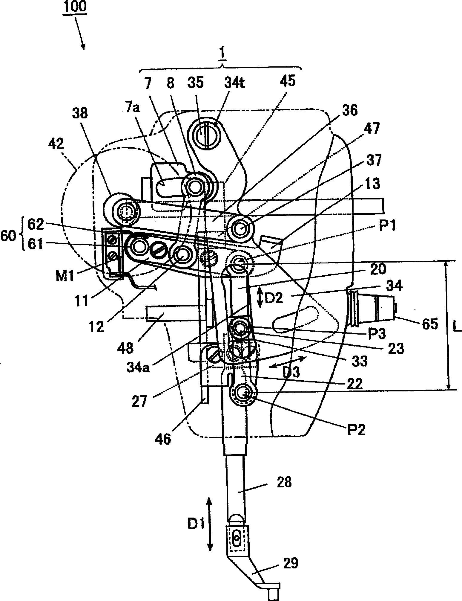
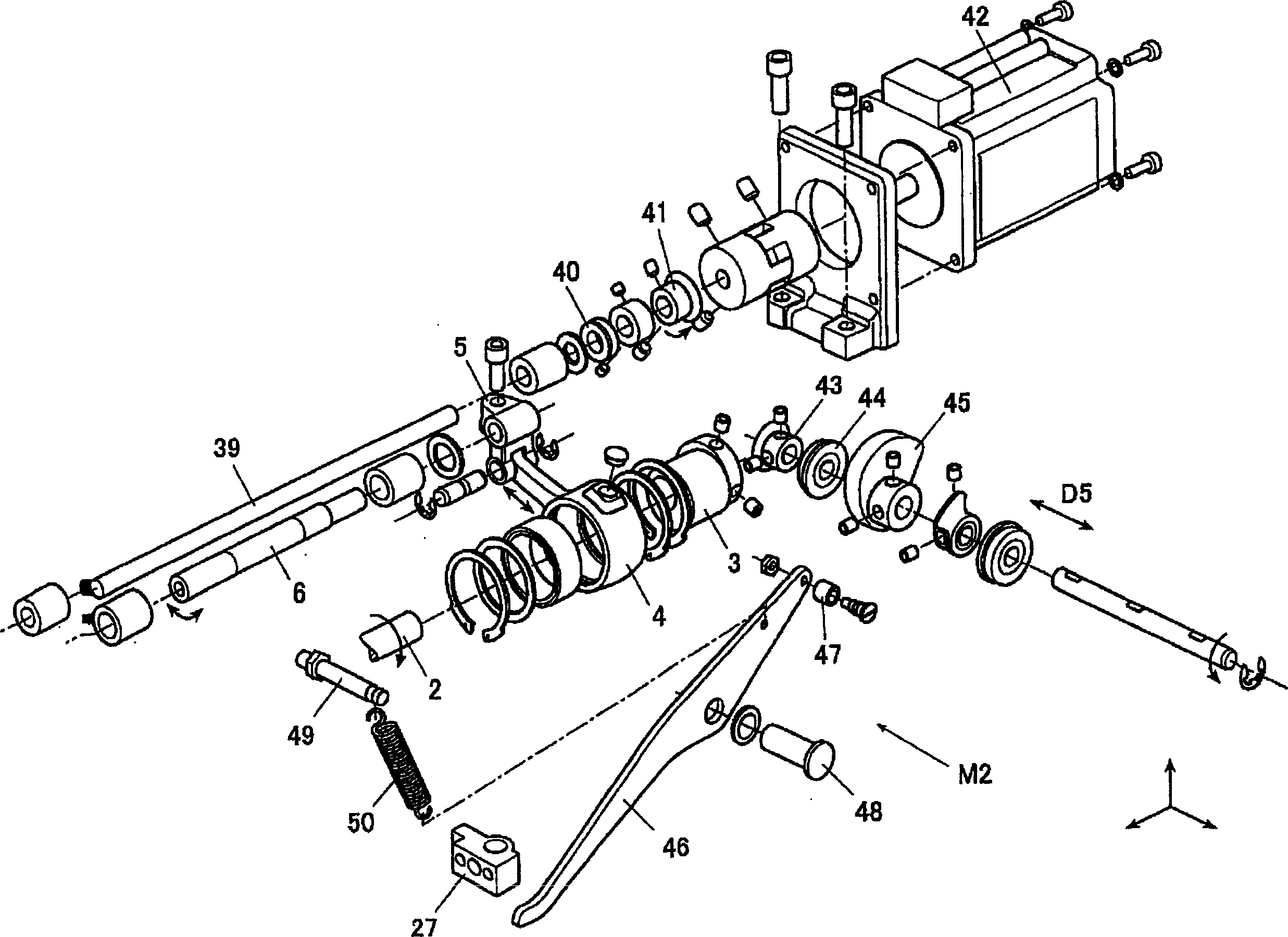
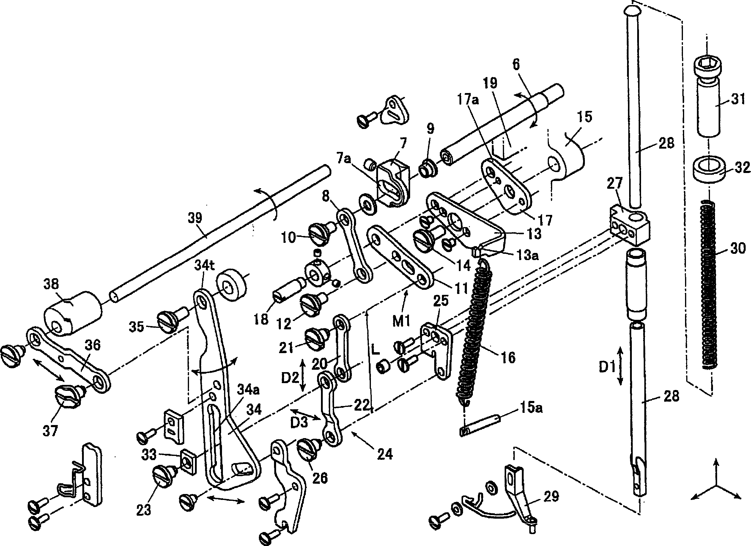
[0054] figure 1 It is a left side view of the main part of the sewing machine 100 in this embodiment viewed from the front side, figure 2 yes figure 1 An exploded perspective view of a part of the shown main part, image 3 yes figure 1 An exploded perspective view of the composition of the remaining part of the main part shown.

[0055] The sewing machine 100 has an unillustrated vertical movement mechanism for moving the needle up and down, a rotary hook mechanism for winding the lower thread and the suture thread inserted into the needle under the needle plate, a cloth holding mechanism as a moving mechanism, and a sewing machine. During sewing, the intermediate presser 29 moves back and forth up and down to press the object to be sewn to the needle plate side, and the intermediate presser as a thickness change detection device detects the thickness change of the fabric through the intermediate presser 29. The foot sen...

Embodiment approach 2

[0161] (summary of embodiment)

[0162] Below, based on Figure 10 ~ Figure 13 A second embodiment, 100A of sewing machines, will be described.

[0163] Such as Figure 10 As shown, the sewing machine 100A is newly equipped with an intermediate presser foot sensor 60A that can detect the amount of change in the up and down movement of the end of the first contact point 61 of the second link 11. The difference from the above sewing machine 100 is that the intermediate presser foot sensor 60A is used to The amount of change in thickness can be obtained when the cloth thickness changes, and motion control can be performed in consideration of the amount of thickness change.

[0164] Only the intermediate presser controller 60A differs from the sewing machine 100 in configurations other than the processing content of motion control. Therefore, in the sewing machine 100A, the same configurations as those in the sewing machine 100 are assigned the same symbols, and only the differe...


PUM


Abstract

A device of the sewing machine is to detect a change of the workpiece (fabric) thickness, composing: an inner foot pushing the workpiece to a needle plate side in sewing, an inner foot driving mechanism applying a reciprocating movement along the vertical direction to the inner foot, and a thickness change detecting device detecting the thickness change of the workpiece via the inner foot. The inner foot driving mechanism is provided with an escape member, when receiving a load exceeding a predetermined amount in lowering of the inner foot, implementing an escape operation instead of a lowering operation of the inner foot. The thickness change detecting means detects the thickness change of the workpiece from the escape operation of the escape member.

Description

technical field [0001] The invention relates to a cloth thickness change detection device of a sewing machine with an intermediate presser foot. Background technique [0002] In the past, such as embroidery sewing machines, in the sewing machine that does not use the feed dog and feeds the cloth in the XY direction while sewing, in order to prevent the cloth and the needle from rising due to the friction between the cloth and the needle It has an intermediate presser that presses down the periphery of the needle penetration part of the fabric when the needle is raised to prevent confusion. Usually, when the needle is lifted from the fabric, the fabric is pressed down by the intermediate presser, and the intermediate presser and the needle rise together after the needle is fully lifted from the fabric. [0003] In addition, the above-mentioned conventional sewing machine has a thickness detection mechanism for detecting a change in the thickness of the cloth on the needle pl...

Claims


Application Information

Patent Timeline
Patent Type & Authority Applications(China)
IPC IPC(8): D05B29/02D05B19/12
CPCD05B19/16D05B29/02D05B29/08D05B47/04D05B57/30D05D2305/32D05D2305/36
Inventor 村井健二
Owner JUKI CORP
Learn More