
Automatic electric resistance welding equipment for hoop spring hook

A spring hook, resistance welding technology, applied in resistance welding equipment, welding equipment, welding equipment and other directions, can solve the problems of complex spring hook shape, long welding time for a single piece, difficult quality control, etc., to improve working conditions and welding time. Long, smooth appearance weld

Inactive Publication Date: 2006-07-12
孙光斌
View PDF1 Cites 4 Cited by
  • Summary
  • Abstract
  • Description
  • Claims
  • Application Information

AI Technical Summary

Problems solved by technology

[0002] At present, there are many kinds of resistance welding equipment, but many welding workpieces are still manually operated. For example, the 12 spring hooks used for hanging basketball nets on the basketball hoop are all manually operated by each spring hook. Machine welding is fixed on the welded circular ring. Because the shape of the spring hook is complex and difficult to place, it takes a long time to weld a single piece. In addition, the spring hook also has requirements for positioning welding, size, appearance quality, and beautiful finish. People with certain skills and experience are required to operate, and the quality is difficult to control
[0003] Patent No. 200520018901.X "A Ball Connecting Rod and Push Rod Resistance Welding Equipment" also provides a welding equipment for welding auto parts, steel balls or ball seats and rods or tubes, and can meet high precision, high Strength welding requirements, but it is also a special welding machine

Method used


Image

  • Automatic electric resistance welding equipment for hoop spring hook
  • Automatic electric resistance welding equipment for hoop spring hook
  • Automatic electric resistance welding equipment for hoop spring hook

Examples


Embodiment Construction

[0014] Embodiments of the present invention will be further described below in conjunction with the accompanying drawings.

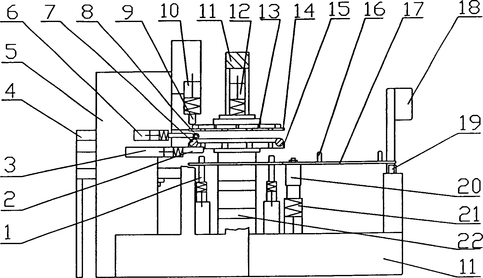
[0015] The automatic resistance welding equipment of the basket spring hook is composed of a feeding mechanism, a resistance welding machine 5, a basket replacement and rotation pressing mechanism and a console 18 fixed on the bracket 11.

[0016] Feeding mechanism: a vibrating motor 25 is installed at the center of the bottom of the discharge tray 4. There is a groove-shaped outlet matching the shape of the spring hook 8 around the discharge tray 4, and a high-pressure gas nozzle 24 is arranged at the outlet, and the gas The station continuously supplies high-pressure gas to the spray head 24 through the pipeline.

[0017] Resistance welding machine 5: the positive electrode 9 and the negative electrode 2 are installed on the cylinder rods of the two cylinders 10 and 3 respectively. The top of the negative pole cylinder seat on the machine is also fixe...


PUM


Abstract

The invention relates to a basket spring hook automatic electric welding device which comprises a feeding device, an electric welding machine, a basket exchange rotation compression device fixed on the support and formed by a rotation lifting device, an air-powered compression device, a servo-rotation device and an air-powered supporting device, and a control board. The basket is arrange don the dual-position clamping-material station of said rotation lifting device; the spring hook via vibration automation discharging and high-pressure air nozzle is blown to the air-powered clamp and absorbed by another air-powered clamp to be transferred to the basket welding position; two electrodes of said electric resistance welding machine will clamp two work-pieces to weld a spring hook via electric loop, then said two electrodes are reset; and the servo-rotation device can rotate the basket for 30 degrees to repeat aforementioned steps until welding 12 spring hooks on the basket. The inventive device has the advantages of lower technique demand; continuous operation; improved efficiency; quick operation of air-powder clamp; accurate welding positioning; improved product quality; and smooth welded appearance.

Description

technical field [0001] The invention relates to a resistance welding equipment, in particular to a special equipment for welding multiple spring hooks with complex shapes on the same part basket ring spring hook automatic resistance welding equipment. Background technique [0002] At present, there are many kinds of resistance welding equipment, but many welding workpieces are still manually operated. For example, the 12 spring hooks used for hanging basketball nets on the basketball hoop are all manually operated by each spring hook. Machine welding is fixed on the welded circular ring. Because the shape of the spring hook is complex and difficult to place, it takes a long time to weld a single piece. In addition, the spring hook also has requirements for positioning welding, size, appearance quality, and beautiful finish. People with certain skills and experience are required to operate, and the quality is difficult to control. [0003] Patent No. 200520018901.X "A Ball C...

Claims


Application Information

Patent Timeline
Patent Type & Authority Applications(China)
IPC IPC(8): B23K11/11B23K11/36B23K37/04
Inventor 严望军
Owner 孙光斌
Learn More