
Interpretation method for touch controlled induction system

A touch sensing and touchpad technology, applied in the input/output process of data processing, instruments, electrical and digital data processing, etc., can solve the effect of the uniformity of equivalent capacitance, the increase of space, and the poor sensing range and sensitivity And other issues

Inactive Publication Date: 2006-07-05
HOLTEK SEMICON
View PDF0 Cites 72 Cited by
  • Summary
  • Abstract
  • Description
  • Claims
  • Application Information

AI Technical Summary

Problems solved by technology

[0010] Among the above three methods, although the memory space used by the first and second methods is very low, the sensing range and sensitivity will become very poor with the increase of touch keys; The equivalent capacitance of the button will vary with the uniformity of the board, board thickness, and copper thickness, which will seriously affect the uniformity of the equivalent capacitance, resulting in differences in the potential charged by the equivalent capacitance of each button, so if Compared with the previously recorded potential, misjudgment often occurs, and it is also more susceptible to interference from external factors
[0011] Although the third method can effectively improve the sensing range and sensitivity of the touch sensing device, if it is used in a large number of keys (for example: hundreds of keys), it will obviously take up more space on the memory, here At the same time, if the bits of the analog / digital circuit in the touch sensing device are higher, the memory space occupied by it will be larger, and the addition and multiplication of the two will make the processing speed of the overall device slower and the calculation speed lower.

Method used


Image

  • Interpretation method for touch controlled induction system
  • Interpretation method for touch controlled induction system

Examples


Embodiment Construction

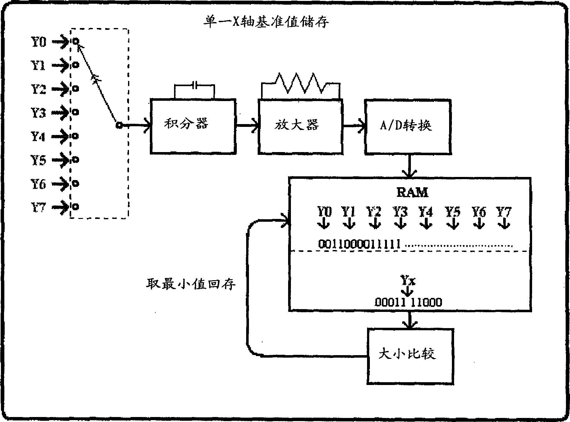
[0020] The principle adopted in the present invention is that firstly, the charging potential value of a certain button on each X-axis must be stored as the potential reference value, and the integral capacitance potential value of this button must be the lowest on the coaxial axis, so as to provide the charging potential value of each button. Comparing the charging potential, when a hand touches the charge energy on the button will be attracted by the finger, and at this time the charging potential of the button must be lower than the potential reference value of the original button, at this time the microcontroller can judge that the button is At that point the key was pressed.

[0021] now to cooperate figure 1 and figure 2 The structural diagram and schematic diagram of the embodiment of the present invention will be described:

[0022] see figure 1 , which is a structural schematic diagram of the capacitive touch sensing device of the present invention. As shown in th...


PUM


Abstract

The invention is a determining method for a touch control induction device comprising a touch control pad at least connected to m X n equivalent capacitors, where m is number of equivalent capacitors in the X-axis direction and n is that in the Y-axis direction, and the determining method comprises the steps of: charging m equivalent capacitors of a column to obtain m digital signals; comparing them with one another and using the smallest as a potential reference value; repeating the above two steps to obtain n potential reference values; touching the touch control pad; scanning the touch control pad to obtain at least a potential variation value relative to m equivalent capacitors of at least a column; and comparing the potential reference value with the potential variation value to determine which point in this column on the touch control pad is touched.

Description

technical field [0001] The invention refers to a method for interpreting a touch sensing device, in particular to a method for interpreting a capacitive touch sensing device. Background technique [0002] General touch sensing devices can be divided into resistive and capacitive in terms of system design. Taking the commonly used capacitive touch sensing devices as an example, there are currently three detection methods in use, which are briefly described as follows: [0003] (1) Record the potential of one of the touch buttons and compare it with the charging potential of all the buttons. The microcontroller will finally know which button is pressed: [0004] First, the microcontroller will enter the stage of storing the potential reference value, and the system will send a continuous pulse wave to the equivalent capacitance of the touch panel, and a charge energy will be induced at the other end of the capacitor, and the charge will be stored in the capacitor through the i...

Claims


Application Information

Patent Timeline
Patent Type & Authority Applications(China)
IPC IPC(8): G06F3/044
Inventor 林怡诚
Owner HOLTEK SEMICON
Learn More