Floating damper

A technology of buffers and buffer devices, which is applied in the direction of hoisting devices, portable lifting devices, wing fan parts, etc., and can solve problems such as misalignment of related components and increase the severity of problems

Active Publication Date: 2006-07-05
ILLINOIS TOOL WORKS INC
View PDF0 Cites 3 Cited by
  • Summary
  • Abstract
  • Description
  • Claims
  • Application Information

AI Technical Summary

Problems solved by technology

Long-term use and wear may also cause misalignment of related components, increasing the severity of the problem

Method used


Image

  • Floating damper
  • Floating damper
  • Floating damper

Examples


Embodiment Construction

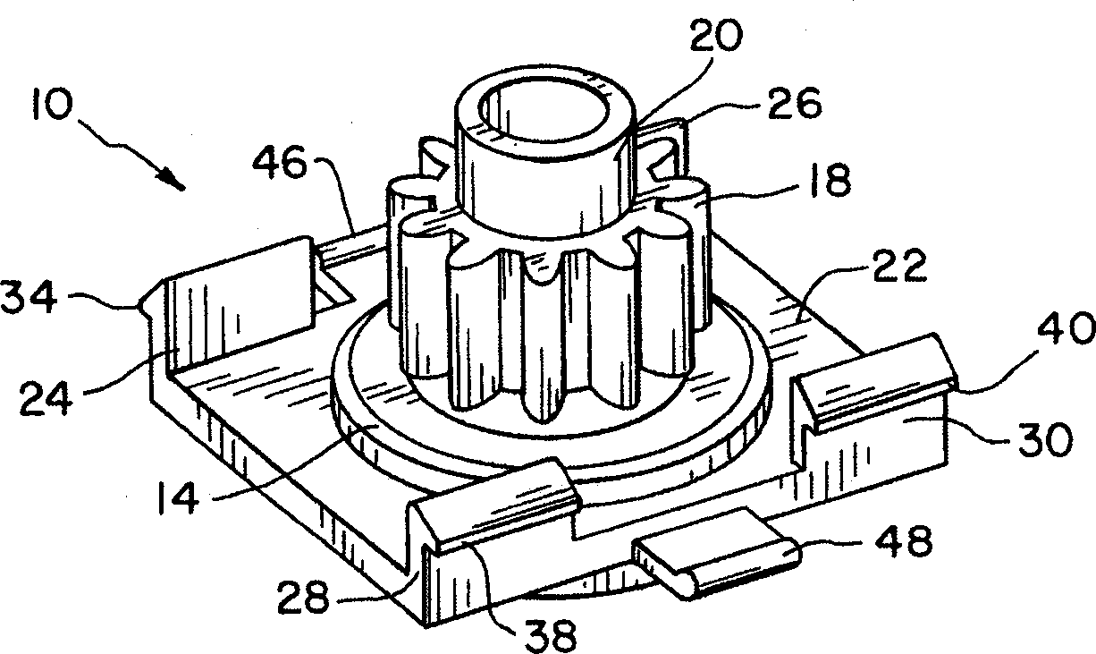
[0024] Referring now more particularly to the drawings, and in particular to figure 1 , reference numeral 10 represents the buffer of the present invention, which can be used to install in the device ( figure 2 ), which may be a door, frame or panel of a glove box or a parts box; a cup holder in an automobile, etc.; or a drawer, door on other equipment and structures such as furniture, instruments, electronic components, etc. , devices and objects. It is envisioned that the snubber 10 of the present invention has a wide variety of uses and uses, and the snubber should not be construed as limited to the few applications and uses exemplified herein.

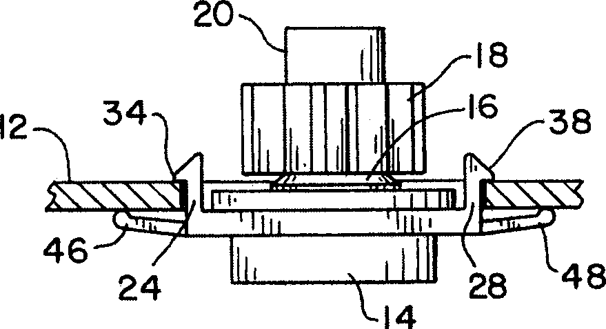
[0025] The damper 10 includes a housing 14 and a rotor rotatably disposed therein. The rotor includes a shaft 16 extending out of the housing 14 . The gear 18 is in drive connection with the shaft 16 and rotates with the shaft 16 . The ends of the damper gear 18 form outwardly a bearing surface 20 . Shaft 16, snubber gear 18 ...


PUM


Abstract

A floating buffer arrangement operates between first and second associated components. A bumper is adjustably mounted on the first member and includes a bumper gear that engages a gear on the second member. The second part is provided with a guide surface, and the buffer has a bearing surface cooperating with the guide surface.

Description

[0001] Cross-references to related applications [0002] This US patent application claims the benefit of US Provisional Patent Application No. 60 / 629,044, filed November 18, 2004. technical field [0003] The present invention relates generally to floating damper devices and, more particularly, to small gear dampers using damping media or fluids as the damping means. Background technique [0004] Small bumpers have many uses and are used to control the motion of objects. Bumpers are commonly used in automobiles, such as glove box doors, cup holders, auxiliary handles, etc. The bumpers are used to control the natural gravitational motion of these parts and to provide the desired "touch" to the motion of the parts. In addition to automobiles, bumpers are known to be used in such devices as, but not limited to, furniture, instruments, electronic equipment and other devices having moving parts. [0005] A commonly used snubber design is known to provide resistance to gear mo...

Claims


Application Information

Patent Timeline
Patent Type & Authority Applications(China)
IPC IPC(8): F16H55/02F16H55/26
CPCE05Y2900/538
Inventor 贾米森・J.安顿斯蒂文・L.比文斯大卫・A.多恩伯斯
Owner ILLINOIS TOOL WORKS INC
Why Eureka
Try Eureka