Eureka AIR delivers breakthrough ideas for toughest innovation challenges, trusted by R&D personnel around the world.

Biological reactor for treating sewage

A bioreactor and sewage treatment technology, which is applied in the direction of biological water/sewage treatment, water/sludge/sewage treatment, aerobic process treatment, etc., can solve the difficulty of assembly and processing of the shroud and the effect of sewage purification It is not very ideal, the overall device cost is high, etc., to achieve the effect of maintaining stable processing capacity, easy implementation, and reducing implementation cost

Inactive Publication Date: 2006-06-28
ZHEJIANG DEAN TECH
View PDF1 Cites 1 Cited by
  • Summary
  • Abstract
  • Description
  • Claims
  • Application Information

AI Technical Summary

Problems solved by technology

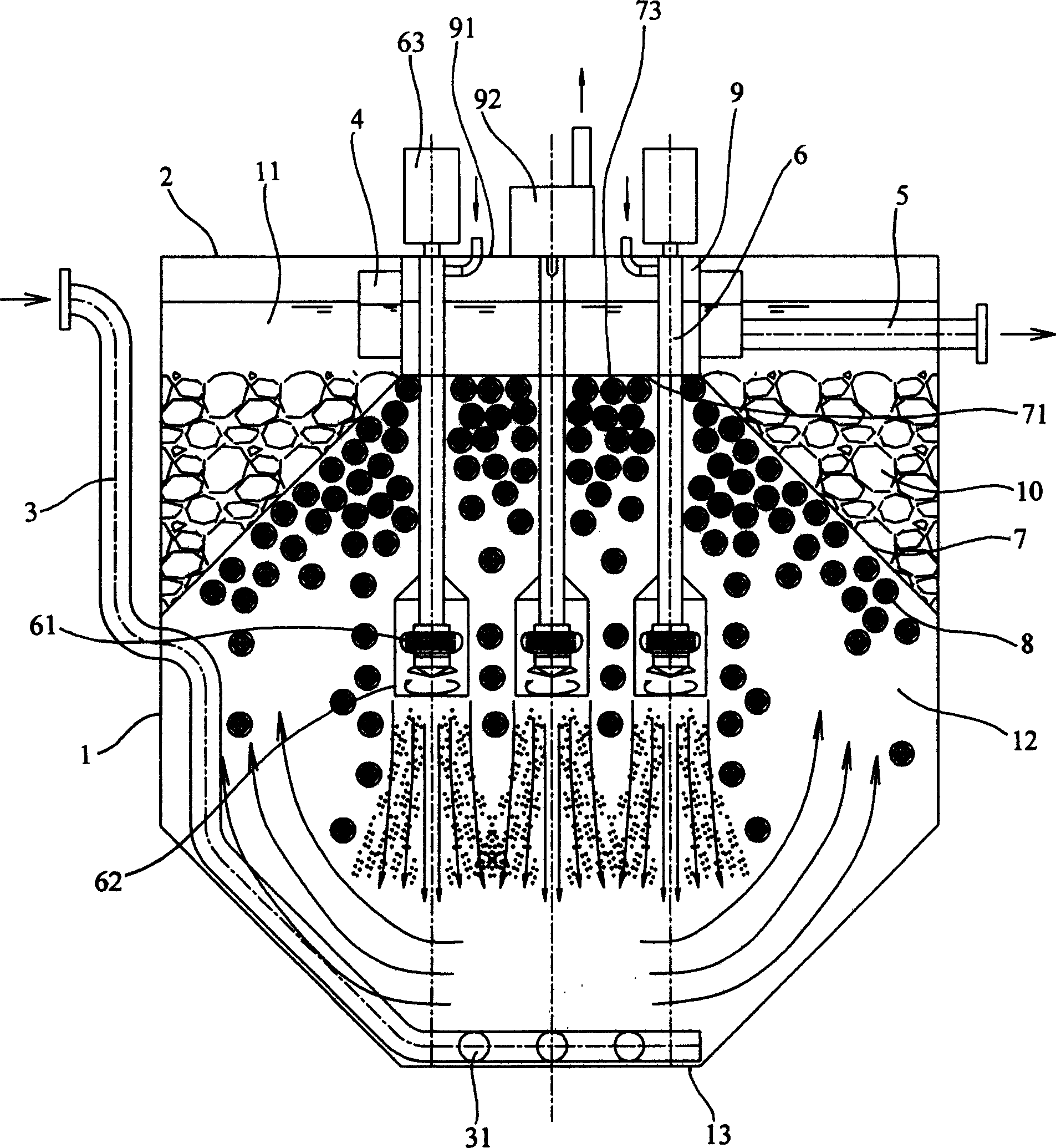
[0003] However, in this kind of bioreactor for sewage treatment, the sewage entering from the water inlet directly reaches the top of the aeration area. Because the sump is located on the top of the aeration area, it is easy to cause the sewage to not undergo sufficient biological reaction, and It is quickly output to the water collection tank, and then flows to the water outlet, which will greatly reduce the sewage purification rate, and the sewage purification effect is not very ideal; moreover, the water flowing through the top of the aeration area directly flows to the At the water outlet, it is easy for the incompletely reacted water flow and impurities to be output to the sump, which will also reduce the purification rate of the sewage; at the same time, because the bioreactor needs to be equipped with two layers of isolation devices inside and outside to form an aeration zone and a sedimentation zone respectively , for a bioreactor with a larger volume, the cost of the overall device will undoubtedly become higher, and the difficulty of assembling and processing the large shroud will increase accordingly, making it difficult to implement in practice

Method used


Image

  • Biological reactor for treating sewage
  • Biological reactor for treating sewage
  • Biological reactor for treating sewage

Examples


Embodiment Construction

[0028] The present invention will be further described in detail below in conjunction with the accompanying drawings and embodiments.

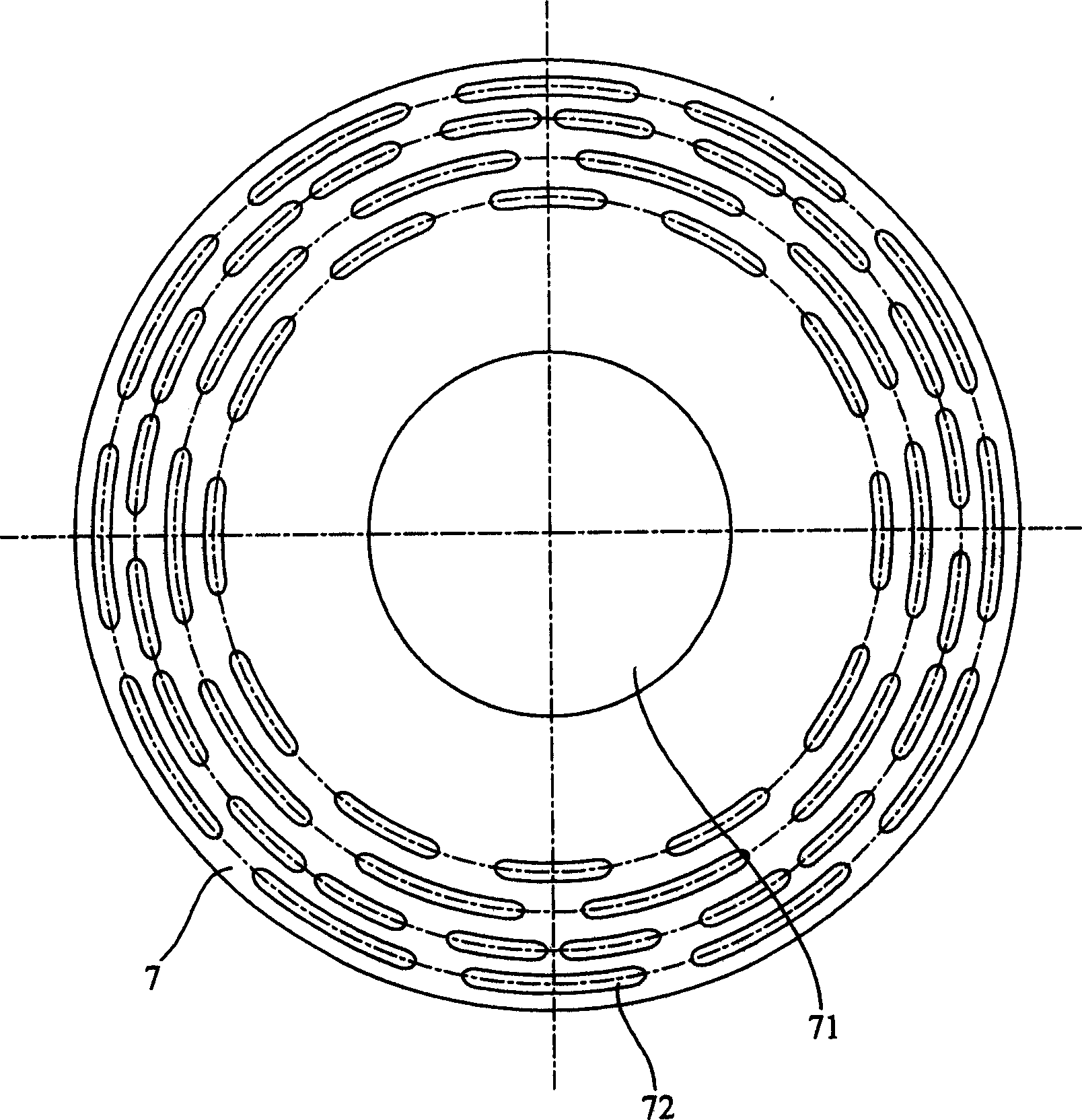
[0029] Such as Figure 1 ~ Figure 3 As shown, the bioreactor for sewage treatment includes a shell 1 and its top cover 2, an inlet pipe 3, a sump 3, and an outlet pipe 5 communicating with the sump 3, which is set in the center of the top cover 2 There is an aerator 6 with a head 61 inserted into the inside of the housing 1, and a ring of porous partitions 7 is arranged along the inner wall of the housing 1 above the head 61 of the aerator 6, and the housing The interior of the body 1 is divided into a biological reaction zone 12 where the head 61 of the aerator 6 is located and a sedimentation catchment area 11 above the porous partition 7, and an active filler 8 is placed in the biological reaction zone 12;

[0030] Wherein, the active filler 8 is an inorganic or organic filler with an approximately spherical structure, and its density is c...


PUM


Abstract

A bioreactor for treating sewage is composed of casing, top cover, water inlet tubes extended to bottom of casing, water collector, water outlet tube, aerator, active filler, and a ring-shaped multi-hole plate to divide the internal space of casing into bio-reaction region and depositing-water collecting region and form an air outlet.

Description

technical field [0001] The invention relates to the technical field of sewage treatment, in particular to a bioreactor for sewage treatment. Background technique [0002] With the continuous shortage of water resources and the continuous strengthening of environmental pollution control, people have begun to pay attention to the treatment of sewage generated in various places and reuse it as much as possible. At present, the methods of treating the generated sewage can be roughly divided into activated sludge method, biological filter method, biological contact oxidation method, etc., and they are carried out step by step and need to occupy a large pool capacity. Therefore, There are defects such as scattered structure, large space occupation, high investment cost, long process flow, unsuitable management, and difficult maintenance and repair, and make it difficult to popularize in small-scale and decentralized sewage treatment occasions. Therefore, some sewage treatment equ...

Claims


Application Information

Patent Timeline
IPC IPC(8): C02F3/02C02F3/10
CPCY02W10/10
Inventor 俞建德
Owner ZHEJIANG DEAN TECH
Why Eureka
Eureka Blog
Learn More