
Conductive frequency selective surface utilizing arc and line elements

A frequency-selective, arc-shaped technology, applied to electrical components, antenna components, antennas, etc., can solve the problem of not eliminating the defects of the frequency-selective surface

Active Publication Date: 2006-06-07
VITRO FLAT GLASS LLC
View PDF21 Cites 16 Cited by
  • Summary
  • Abstract
  • Description
  • Claims
  • Application Information

AI Technical Summary

Problems solved by technology

[0010] While currently available frequency selective surfaces reduce the difference between visible light transmission and opening of the coating to make windshields aesthetically acceptable, they do not eliminate the drawbacks of using frequency selective surfaces with heatable coatings

Method used


Image

  • Conductive frequency selective surface utilizing arc and line elements
  • Conductive frequency selective surface utilizing arc and line elements
  • Conductive frequency selective surface utilizing arc and line elements

Examples


Embodiment Construction

[0041] Before discussing non-limiting embodiments of the present invention, it is to be understood that the present invention is not limited in application to the details of the particular embodiment shown and discussed, for the invention can be practiced in other embodiments. Also, the examples used herein are for purposes of illustration and not limitation.

[0042] As used herein, spatial or directional terms such as "inner," "outer," "left," "right," "upper," "lower," "horizontal," "vertical," etc. As shown in the figure. It should be understood, however, that the invention may assume a variety of alternative orientations and, therefore, these terms are not to be considered limiting. Further, all numbers expressing dimensions, physical characteristics, etc. used in the specification and claims should be understood as being modified by "about" in all cases. Accordingly, unless indicated to the contrary, numerical values ​​set forth in the specification and claims may vary...


PUM

PropertyMeasurementUnit
lengthaaaaaaaaaa
heightaaaaaaaaaa
thicknessaaaaaaaaaa

Abstract

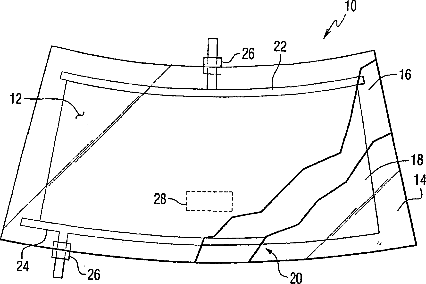
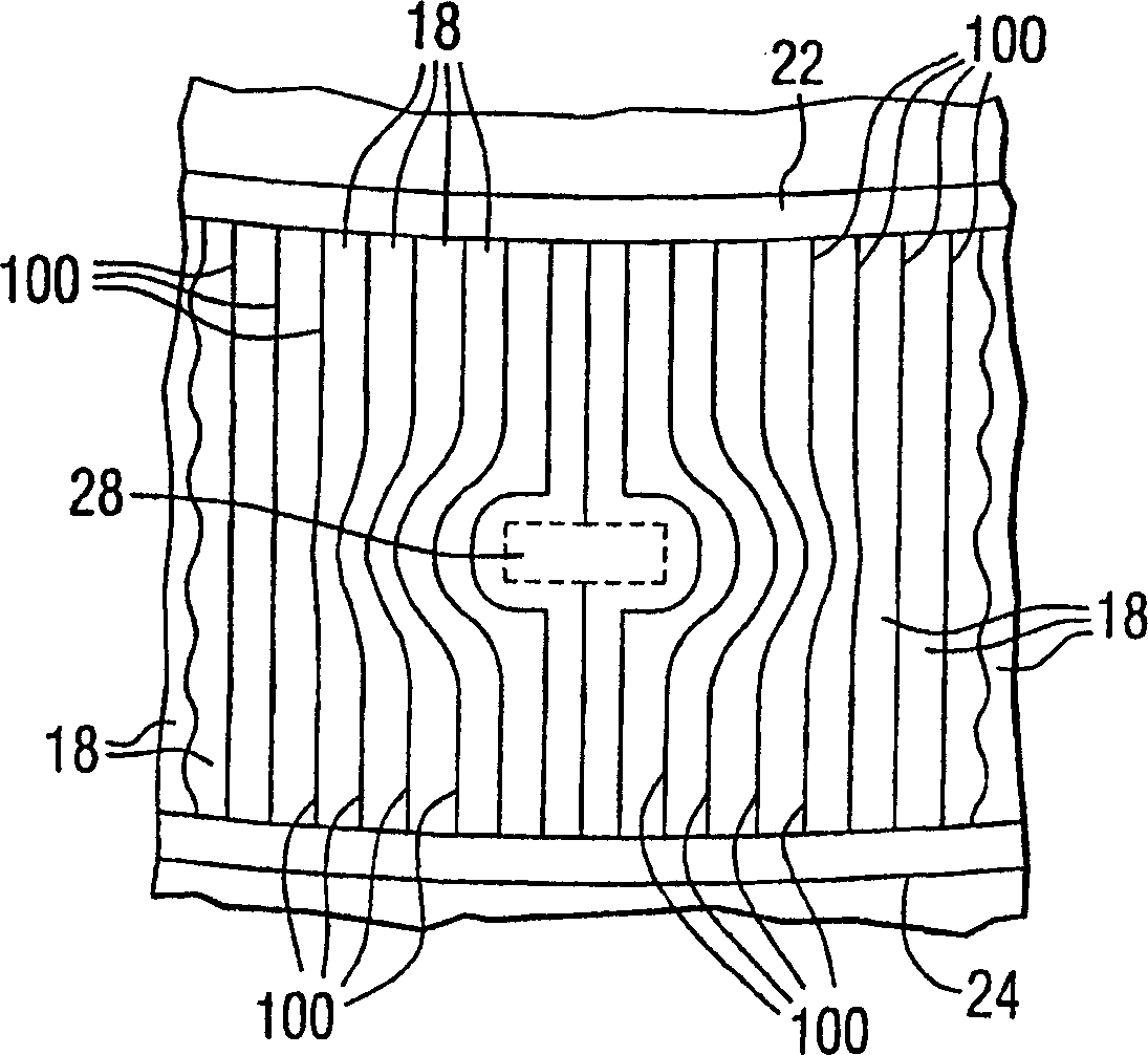
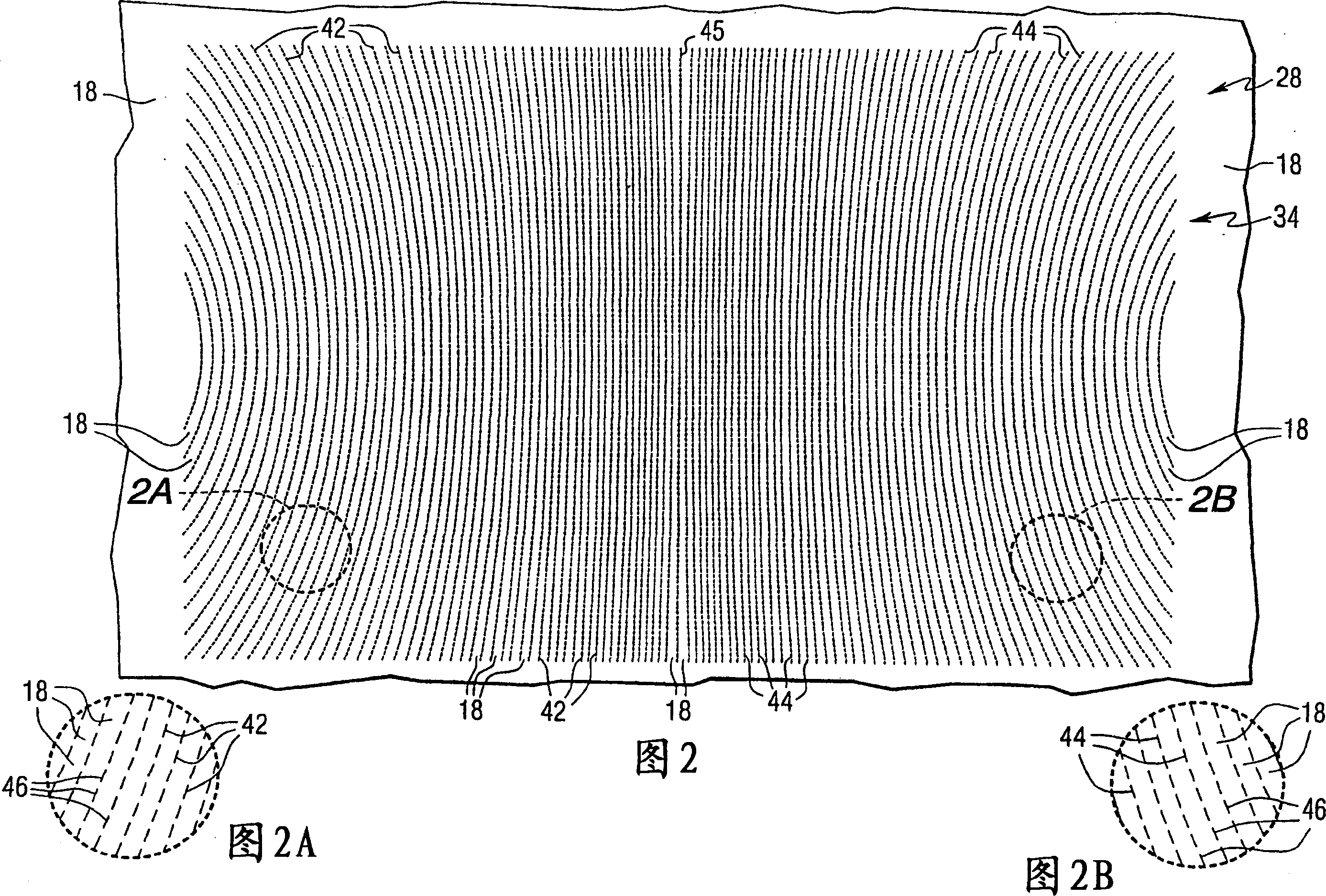
An electrically conductive coating for an automotive heatable windshield having a communication window with an enhanced frequency selective surface having pass regions (uncoated regions) and blocking regions (coated regions) arranged to pass and Blocks predetermined wavelengths of the electromagnetic spectrum. In one non-limiting embodiment, the frequency selective surface includes a pattern having a first plurality of arcuate discontinuities on one side of the delimiting discontinuities, and a second plurality of arcuate discontinuities on the other side of the delimiting discontinuities. Multiple arc breaklines. Extended continuous barrier areas are between adjacent discontinuous lines. The arcuate discontinuities of one group are embedded within each other, and the arcuate discontinuity having the largest radius of curvature adjacently divides the discontinuity. Each discontinuous line has alternating blocking and passing regions. In another embodiment, the enhanced frequency selective surface has a plurality of columns separated from each other by continuously elongated blocking regions. Each column includes a pass area, and each pass area has a perimeter, and the block area is within and spaced from the perimeter. The perimeters of the pass regions are in contact with each other, and the barrier regions adjacent to the pass regions are spaced apart from each other. The elongated blocking area between the discontinuity and the column extends to the perimeter of the communication window. In this manner, current is passed through the coating, through the communication window to eliminate hot and cold spots around and within the perimeter of the communication window.

Description

[0001] related application [0002] Interlayer composites disclosed in U.S. Patent Application Serial No. 10 / 201863 filed July 24, 2002 by Bruce Bartrug, Allen R. Hawk, Robert N. Pinchok, and James H. Schwartz, entitled "Laminated Edge Sealing of Transparencies"; Allen R. Hawk's U.S. Patent Application Serial No. 10 / 201864, filed July 24, 2002, discloses a bus bar layout entitled "Eliminating the Hotspots at the ends of busbars that heat transparent sheets"; U.S. Application Serial No. 10 / 264,106 heatable article filed October 3, 2002 by Charles S. Voeltzel, entitled "Heatable Articles with Disposed Heating Elements," and Glenn E. Freeman, Robert C. Lewetag, and James P. Thiel, disclosed in U.S. Patent Application Serial No. 10 / 353,566, filed January 29, 2003, for preventing edge corrosion of laminate-coated articles, which Entitled "Coated Articles Having Sealed Laminated Edges to Resist Corrosion of Edge Coatings and Methods of Making Same", these are useful in the present in...

Claims


Application Information

Patent Timeline
Patent Type & Authority Applications(China)
IPC IPC(8): H05B3/84B32B17/10H01Q1/12H01Q1/42H01Q15/00H05B3/86
CPCB32B17/10036B32B17/10174B32B17/10761H01Q1/1271H05B3/84H05B3/86H05B2203/008H05B2203/013H01Q15/0013C03C27/10C03C17/36C03C17/3673C03C17/3644C03C2217/944C03C2218/328
Inventor 查尔斯·S·弗尔茨尔
Owner VITRO FLAT GLASS LLC
Learn More