
Gear device

A technology of gear devices and internal gears, which is applied in the direction of gear transmission devices, winch devices, transmission devices, etc., can solve the problems of the decrease of the coaxiality of the central axis, the increase of cost, and the decrease of the roundness of the ring part of the internal gear, etc. Effects of retention, improvement of bonding strength, and cost reduction

Active Publication Date: 2006-05-31
DENSO CORP +1
View PDF1 Cites 3 Cited by
  • Summary
  • Abstract
  • Description
  • Claims
  • Application Information

AI Technical Summary

Problems solved by technology

[0004] Therefore, it is necessary to consider the following structure, that is, holes are opened on the annular end surface of the ring portion of the internal gear and the annular end surface of the cylindrical press-fitting portion (fitting wall) of the housing, and parts such as pins or keys are inserted into the holes. Alternatively, on the annular end surface of the ring portion of the internal gear, a cylindrical protrusion that can be pressed into the hole of the housing is provided by plastic processing to add a stop mechanism for the internal gear, but this will be due to the newly added pin. or keys, etc., or increase the forging process for forming the protruding part, resulting in a problem of cost increase
[0005] Furthermore, as a method of fixing the outer peripheral portion of the ring portion of the internal gear to the inner peripheral portion of the housing fitting wall, a method of caulking the inner peripheral portion of the housing fitting wall on the entire circumference of the ring portion of the internal gear may be considered. , but in order to obtain the fixed strength, it is necessary to apply a large load (external force) to the outer peripheral part of the housing fitting wall (the radial direction of the ring part of the internal gear), so the ring part of the internal gear will produce plasticity in the radial direction deformation, resulting in a reduction in the roundness of the ring portion of the internal gear, which may also cause a decrease in the coaxiality of the central axis of the internal gear and the central axis of the housing fitting wall

Method used


Image

  • Gear device
  • Gear device
  • Gear device

Examples


no. 2 Embodiment

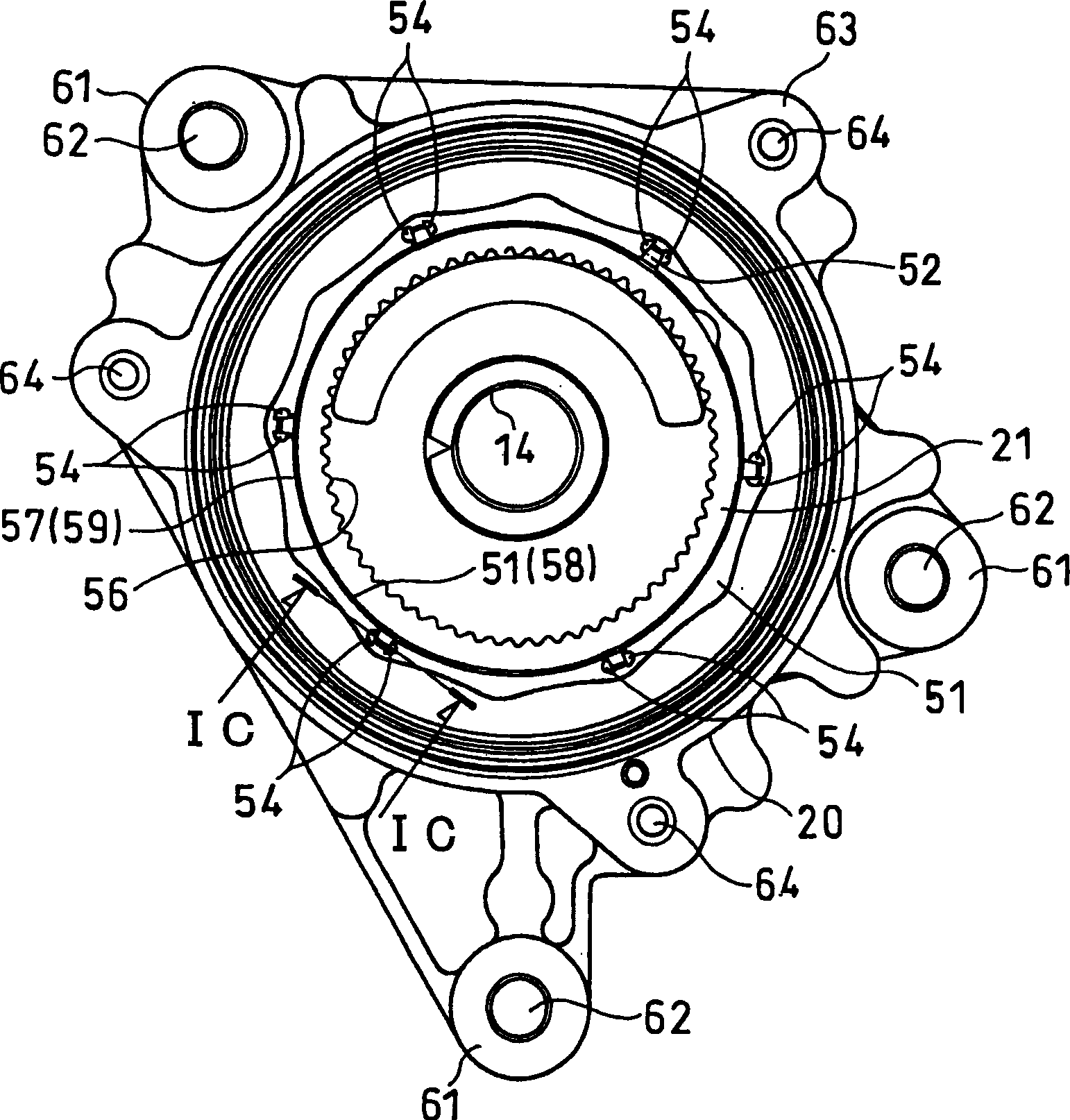
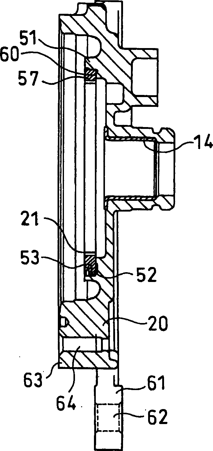
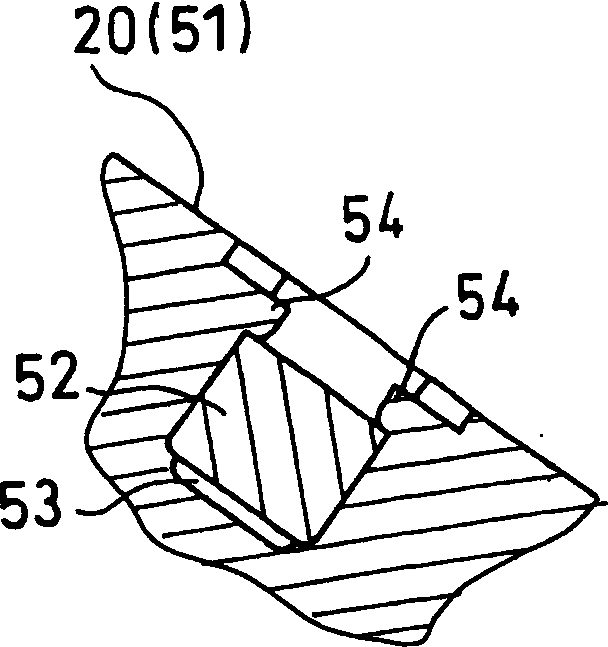
[0068] Figure 4B And what Fig. 5 represented is the 2nd embodiment of the present invention, Figures 4A-4B as well as Figures 5A-5B Shown are the engagement claws of the internal gear of the reduction gear unit and the engagement grooves of the front housing.

[0069] Figure 4A It shows that in the reduction gear device of the first embodiment, the outer peripheral portion of the annular portion 57 of the internal gear 21 is press-fitted into the inner peripheral portion of the fitting wall 51 of the front housing 20, and the The state when the plurality of engaging claws 52 on the outer peripheral portion of the annular portion 57 of the internal gear 21 are fitted into the plurality of engaging grooves 53 provided on the inner peripheral portion of the fitting wall 51 of the front housing 20 .

[0070] At this time, the small gap between the circumferential side surface of the engaging claw 52 and the circumferential side wall surface of the engaging groove 53 is usua...


PUM


Abstract

The invention provides a toothed gearing, in which the peripheral part of internal gear circular part is press-inserted to the internal peripheral part of the front casing built-in wall. After a plurality of clamping catches are inserted in lots of clamping slots on the internal peripheral part of the front casing built-in wall, the two ends of clamping catches are applied the outside force to make them plastically deform, so as to form a plurality of riveted fixing part.

Description

technical field [0001] The present invention relates to a gear device, which is a gear device in which an internal gear is press-fitted on the inner circumference of a fitting wall of a casing, and particularly relates to a reduction gear device such as a cycloidal reducer, which can drive a motor, etc., with a predetermined reduction ratio. The speed of the drive unit is decelerated. Background technique [0002] In the past, the following schemes (for example, Japanese Patent Application Laid-Open No. 2000-274494, refer to pages 1-5, FIGS. 1-4 ) have been proposed, that is, high The outer circumference of the ring part of the inner gear made of rigid metal material is press-fitted to the inner circumference of the cylindrical press-fit part (fitting wall) of the housing made of light metal material such as die-casting aluminum, so that the inner gear Combine the two parts with the shell. [0003] In a conventional planetary gear device, the outer periphery of the annular...

Claims


Application Information

Patent Timeline
Patent Type & Authority Applications(China)
IPC IPC(8): F16H55/17F16H1/28F16H57/08
Inventor 吉山茂木村纯佐佐木一路井上雄二
Owner DENSO CORP
Learn More