


Quick Research
Generate reliable direction feasibility study reports for your R&D in just a few steps.

Technical Q&A
Discover and master advanced knowledge NOW. Basics, ideas, possibilities, all at once.

Find Solutions
As an expert in R&D theories, this can generate solutions to your technical problems instantly.

Evaluate Feasibility
Analyze your overall solution with one click, know your potential R&D risks in advance.

Monitor Landscape
Get weekly tech updates, stay abreast of the latest tech innovations and key insights.
Solid-state imaging device
A technology of solid-state imaging devices and components, which is applied in the direction of electrical components, image communication, color TV components, etc., can solve the problems of high-light area dynamic range and contrast reduction, less wide dynamic range, display discontinuity characteristics, etc., to achieve Realize the effect of wide dynamic range and high use value
- Summary
- Abstract
- Description
- Claims
- Application Information
AI Technical Summary
Problems solved by technology
Method used
Image


Examples
Embodiment 1
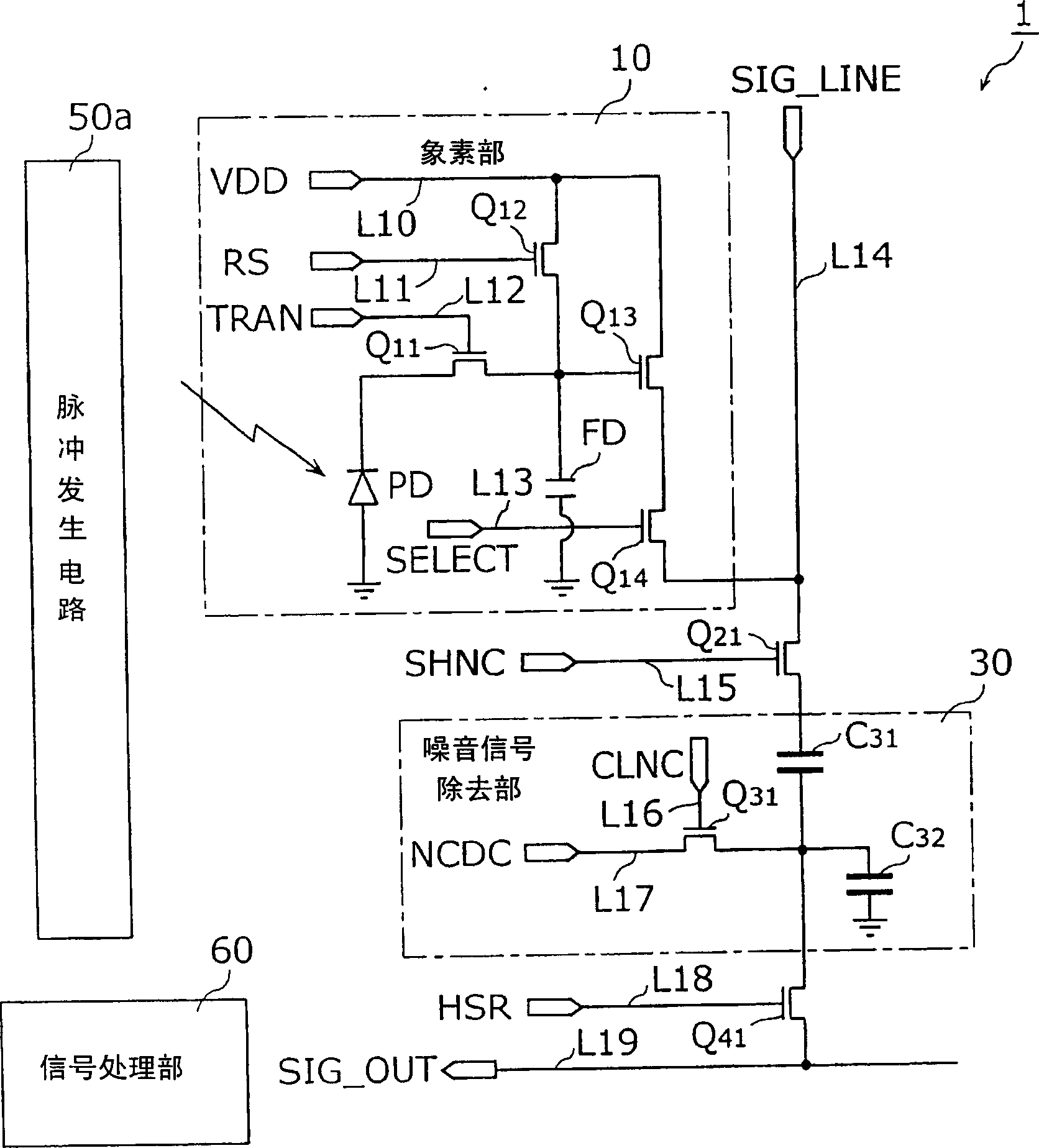
[0066] image 3 It is a circuit diagram showing the structure of the solid-state imaging device according to Embodiment 1 of the present invention. Also, although multiple photoelectric conversion units are provided in the row direction and column direction, image 3 Only one of them is shown in.
[0067] Such as image 3 As shown, the solid-state imaging device 1 includes a pixel portion 10, a MOS transistor Q21, a noise signal removal portion 30, a MOS transistor Q41, a pulse generating circuit 50a, a signal processing portion 60, a power supply line L10, a reset pulse application signal line L11, and a transmission pulse Application signal line L12, row selection pulse application signal line L13, column direction common signal line L14, sample and hold pulse application signal line L15, capacitor initialization pulse application signal line L16, capacitor initialization bias application line L17, horizontal selection pulse application The signal line L18, and the horizontal o...
Embodiment 2
[0106] Next, a description will be given of an operation in a case where the electric charge at the high light amount and the electric charge at the normal light amount are respectively output from the floating diffusion FD to the column direction common signal line L14.
[0107] Figure 8 It is a timing chart showing the timing of operating the solid-state imaging device 1 according to Embodiment 2 of the present invention.
[0108] In addition, in the figure, Figure 8 (a)~ Figure 8 (c) respectively indicate the reset pulse RS, the transfer pulse TRAN, and the row selection pulse SELECT output from the pulse generating circuit 50a to the pixel portion 10 of the (N-1)th row, Figure 8 (d) to (f) respectively represent the reset pulse RS, the transfer pulse TRAN, and the row selection pulse SELECT output from the pulse generating circuit 50a to the pixel portion 10 of the Nth row, Figure 8 (g) represents the sample and hold pulse SHNC output from the pulse generating circuit 50...
Embodiment 3
[0129] Next, a solid-state imaging device according to another embodiment of the present invention will be explained.
[0130] 10 is a circuit diagram showing the structure of a solid-state imaging device according to Embodiment 3 of the present invention. In addition, although a plurality of pixel portions are actually provided in the row direction and the column direction, FIG. 10 only shows one of them. In addition, with image 3 Corresponding parts of the solid-state imaging device 1 shown have the same reference numerals, and the description is omitted.
[0131] The difference from the case of the second embodiment is that the noise signal removal sections 30a, 30b provided in the solid-state imaging device 2 respectively detect the signal at the time of large light intensity and the signal at the time of normal light volume, and add the signal at the time of large light volume to The signal of the normal light intensity is determined by the addition control unit 70 (comparat...
PUM
 Abstract
Description
Claims
Application Information
 - R&D Engineer
- R&D Manager
- IP Professional
- Industry Leading Data Capabilities
- Powerful AI technology
- Patent DNA Extraction
Browse by: Latest US Patents, China's latest patents, Technical Efficacy Thesaurus, Application Domain, Technology Topic, Popular Technical Reports.
© 2024 PatSnap. All rights reserved.Legal|Privacy policy|Modern Slavery Act Transparency Statement|Sitemap|About US| Contact US: help@patsnap.com