
Modified device for withdrawing yarn of automatic cross-winding apparatus

An automatic device and cross-winding technology, which is applied in the field of yarn unwinding devices, can solve the problems of damaged yarn and high yarn tension, etc., and achieve the reduction of yarn unwinding tension, reduced tension, and smooth yarn The effect of unwinding

Inactive Publication Date: 2006-05-03
SAURER GERMANY GMBH & CO KG
View PDF2 Cites 9 Cited by
  • Summary
  • Abstract
  • Description
  • Claims
  • Application Information

AI Technical Summary

Problems solved by technology

Relatively high yarn tensions are generated with this known yarn guide and there is therefore a risk of yarn damage during rewinding

Method used


Image

  • Modified device for withdrawing yarn of automatic cross-winding apparatus
  • Modified device for withdrawing yarn of automatic cross-winding apparatus
  • Modified device for withdrawing yarn of automatic cross-winding apparatus

Examples


Embodiment Construction

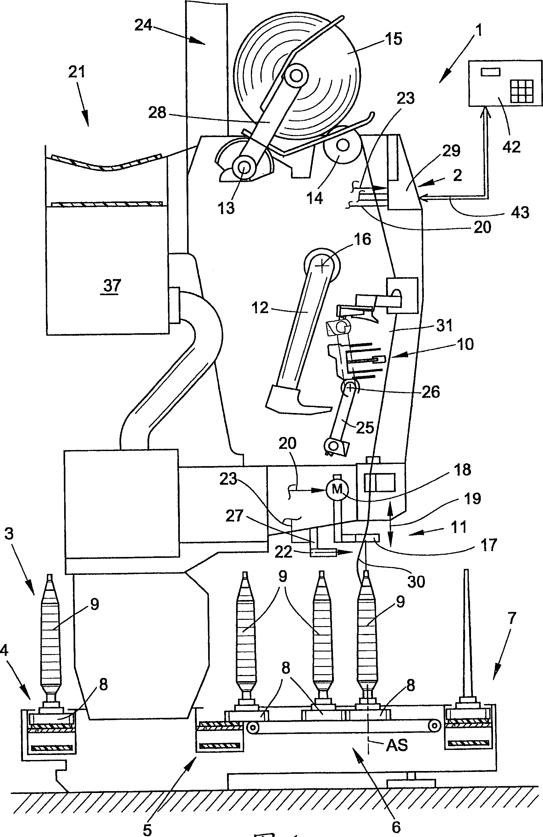
[0032] figure 1 A schematic side view of the cross-winding robot, designated as a whole by the reference numeral 1, is shown. A cross-winding robot 1 of this type usually has a plurality of identical working positions, here winding heads 2 , between its rears (not shown). As is known and therefore will not be described further, via the winding head 2, the bobbin 9 formed on the ring spinning machine is wound into large rolls of cross-wound bobbins 15, which are known according to their processing by means of automatic operating units. (Not shown) The cross-wound bobbin changeover is preferably transferred to the machine-longitudinal cross-wound bobbin conveyor 21 and conveyed to a bobbin handling station or the like arranged on the machine side.

[0033] The cross-winding robot 1 usually also has logic in the form of a winding bobbin delivery system 3 . In the winding bobbin system 3 , the bobbin 9 or the empty bobbin is wound on the delivery disc 8 . exist figure 1Only th...


PUM


Abstract

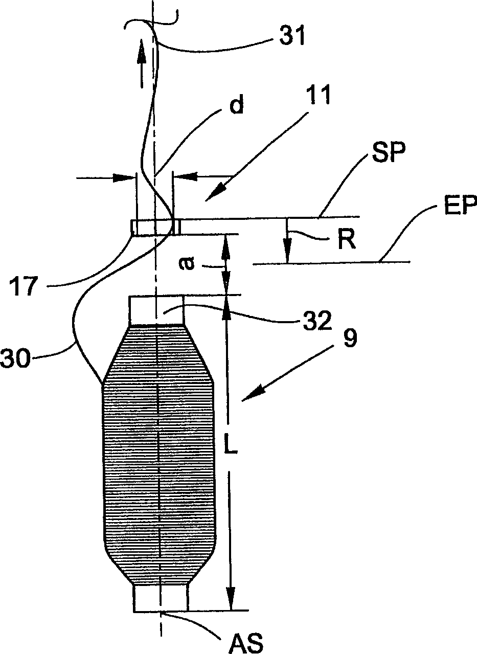
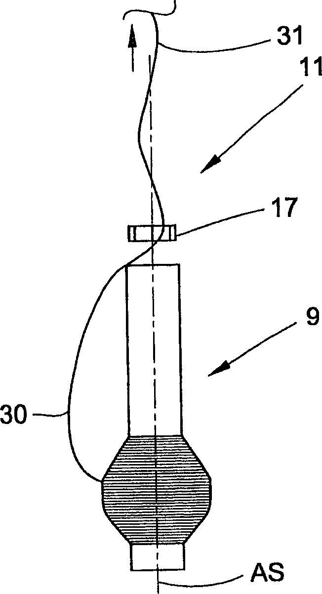
A device for optimizing the yarn unwinding of the winding head of a cross-winding robot, with a vertically moving yarn guide positioned above the unwinding spool, characterized in that a yarn guide (17) is provided The adjusting device (18) of the adjusting device (18) makes the yarn guide (17) which acts as an upper limit on the rotating yarn balloon be positioned vertically in such a way that the formed yarn balloon is a single yarn balloon (30 ), the position of the yarn guide (17) is determined at least according to the winding state of the corresponding unwinding bobbin (9) when the yarn is unwound.

Description

technical field [0001] The invention relates to a device for optimizing the yarn unwinding of the winding head of a cross-winding robot according to the preamble of claim 1 . Background technique [0002] Via the winding head, bobbins, in particular bobbins (Spinnkopse or bobbins) with small yarn weights formed on ring spinning machines are fed and rewound (umspulen) into large cross-wound bobbins. During rewinding, yarn faults are detected, removed and replaced by piecing with approximately yarn uniformity. During the rewinding of the yarn by drawing it through the head of the bobbin forming a so-called yarn balloon, the yarn is subjected to tensile forces whose yarn tension ultimately limits the unwinding speed of the yarn and thus the cross-winding The winding speed of the automatic device. That is to say, during the winding process, if effective precautions are not taken, especially in the last third of the winding process, the yarn tension may increase to several time...

Claims


Application Information

Patent Timeline
Patent Type & Authority Applications(China)
IPC IPC(8): B65H57/22B65H59/06
CPCB65H57/22B65H2701/31
Inventor 莫尼克·格里希-莱费尔德吉多·施皮克斯贝恩德·勒尔施沃尔夫-迈克尔·鲁赫伯特·吕斯肯斯
Owner SAURER GERMANY GMBH & CO KG
Learn More