
Within radius image-dependent detector row filtering method, X-ray CT apparatus and program

A detector and X-ray technology, applied in measuring devices, X-ray equipment, material analysis using wave/particle radiation, etc., can solve problems such as unsatisfactory, high price of scanners, and large-scale processing, so as to suppress artifacts and improve Image quality and the effect of preventing the reduction of z-axis resolution

Active Publication Date: 2006-05-03
TOSHIBA MEDICAL SYST CORP
View PDF4 Cites 4 Cited by
  • Summary
  • Abstract
  • Description
  • Claims
  • Application Information

AI Technical Summary

Problems solved by technology

(2) Scanners are more expensive
(3) A new image reconstruction algorithm is required
These methods all change the core of z-filtering based on object-dependent indices such as gradients in z, requiring a lot of processing, which is not ideal

Method used


Image

  • Within radius image-dependent detector row filtering method, X-ray CT apparatus and program
  • Within radius image-dependent detector row filtering method, X-ray CT apparatus and program
  • Within radius image-dependent detector row filtering method, X-ray CT apparatus and program

Examples


Embodiment Construction

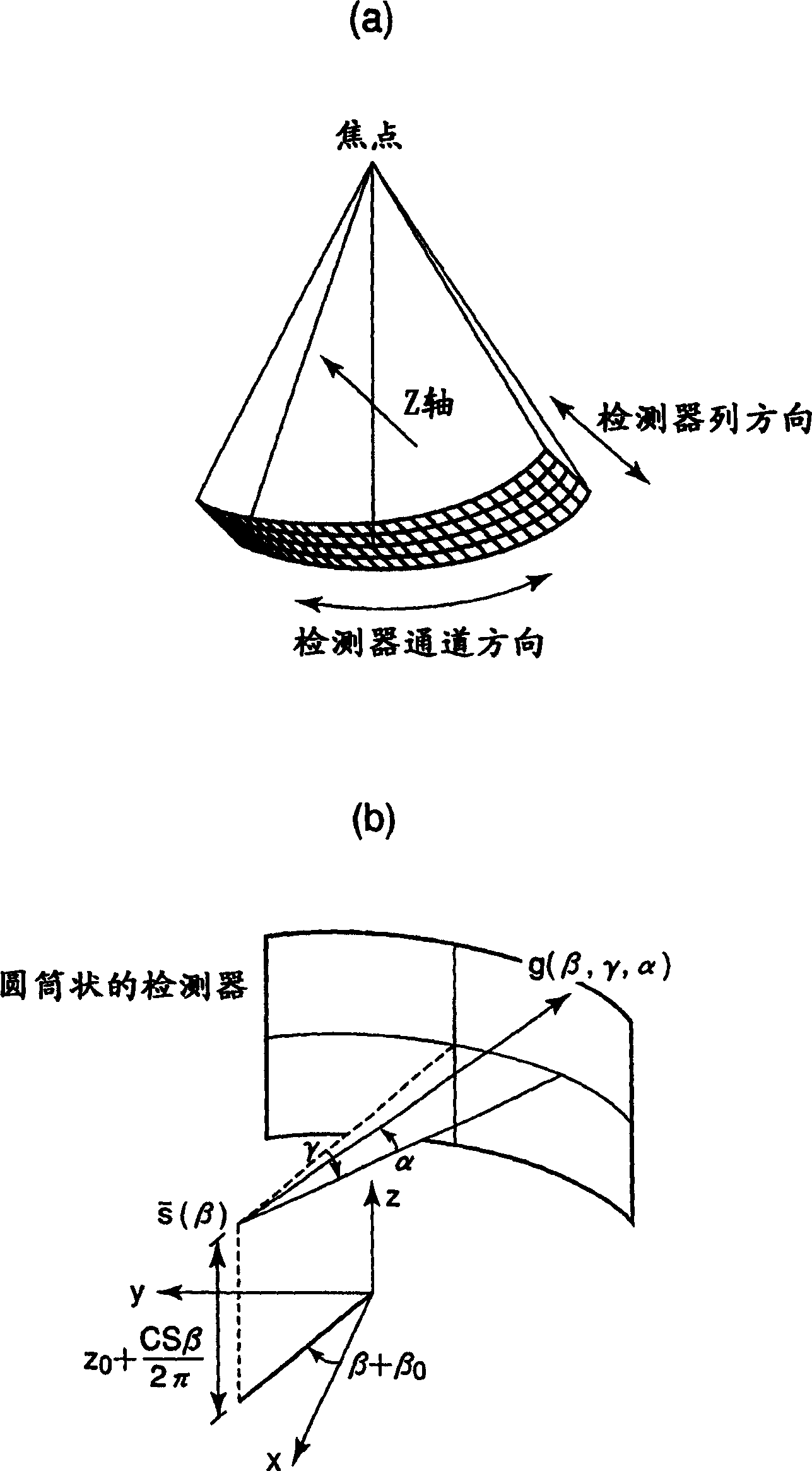
[0053] Figure 8 The configuration of the X-ray computed tomography apparatus (X-ray CT apparatus) according to this embodiment is shown in a block diagram. The rotary scanning device includes a gantry 100 and a bed on which a subject is inserted into an imaging region of the gantry 100 . The gantry 100 has a rotating ring 102 on which a conical beam type X-ray tube 101 and a multilayer X-ray detector 103 are arranged facing each other. The conical beam X-ray tube 101 is configured to receive high-voltage pulses periodically generated from a high-voltage generator 109 via a collar 106, and emit X-rays in the shape of a quadrangular pyramid. The multi-layer X-ray detector 103 is composed of an ionization box-shaped detector box or a semiconductor detector. If it is an ionization box-shaped X-ray detector that can detect multi-layer (multi-column) projection data at the same time, the cone beam The focal point (the apex of the cone beam) of the X-ray tube 101 is the center, an...


PUM


Abstract

A method of acquiring data based on computed tomography scans, acquiring projection data from a detector (103) having a plurality of detector columns in a CT system, and filtering the projection data in the column direction of the detector (103) , the column-direction filtering unit (113) obtains the filtered data with the windmill artifact reduced, and reconstructs the image data from the filtered data using the reconstructed recommended values ​​(114). It can suppress windmilling artifacts and improve image quality while preventing reduction in z-axis resolution.

Description

technical field [0001] The present invention relates to a filtering method, an X-ray CT device and a program of a multi-slice X-ray computed tomography imaging system. Background technique [0002] Multislice X-ray computed tomography (CT) systems were developed and entered the medical market in 1998. Currently, the number of layers generally ranges from 2 to 40, but it is expected to increase to 64 or 256 (see Non-Patent Document 1, Non-Patent Document 2, and Non-Patent Document 3. The contents of each are incorporated herein by reference). Cone beam image reconstruction algorithm using helical scanning for CT system Using Feldkamp algorithm with general weighted Feldkamp reconstruction algorithm, which introduces flexible focus orbit and applies weighting function to Feldkamp algorithm (See Patent Document 1 and Patent Document 2, and Non-Patent Document 4 to Non-Patent Document 10. The contents of each are incorporated herein by reference.) [0003] Among other reconstr...

Claims


Application Information

Patent Timeline
Patent Type & Authority Applications(China)
IPC IPC(8): A61B6/03A61B6/00G01N23/00G01N23/04G21K1/12H05G1/60
CPCA61B6/032G01N23/046A61B6/027A61B6/4021G01N2223/419
Inventor 田口克行
Owner TOSHIBA MEDICAL SYST CORP
Learn More