Dust collector suction nozzle

A suction head and vacuum cleaner technology, applied in the direction of the suction nozzle, etc., can solve the problems that the dust cannot be cleaned cleanly and the suction force is small

Inactive Publication Date: 2006-05-03
LG ELECTRONICS (TIANJIN) APPLIANCES CO LTD
View PDF0 Cites 2 Cited by
  • Summary
  • Abstract
  • Description
  • Claims
  • Application Information

AI Technical Summary

Problems solved by technology

[0012] However, the general upright vacuum cleaner with the above-mentioned structure has the following disadvantages. Under the action of the shaking brush 12, the dust or foreign matter on the floor is swept to the front and rear sides, wherein the dust or foreign matter swept to the front passes through The front suction port 16 sucks into the interior of the dust washer, and the dust or foreign matter swept to the rear is sucked into the interior through the rear suction port 16. From the structure of the rear suction port 16, it is opposite to the rear suction port 16 along the length direction. The suction force on one side is relatively small, so the dust swept to the rear cannot be swept away cleanly

Method used


Image

  • Dust collector suction nozzle
  • Dust collector suction nozzle
  • Dust collector suction nozzle

Examples


Embodiment Construction

[0032] Next, the structure of the suction head of the vacuum cleaner of the present invention will be described in more detail with reference to the embodiments of the accompanying drawings.

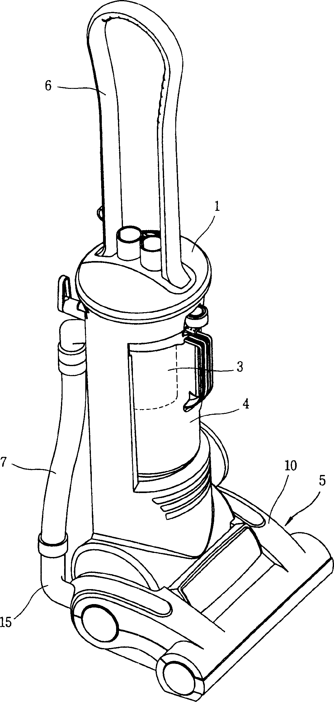
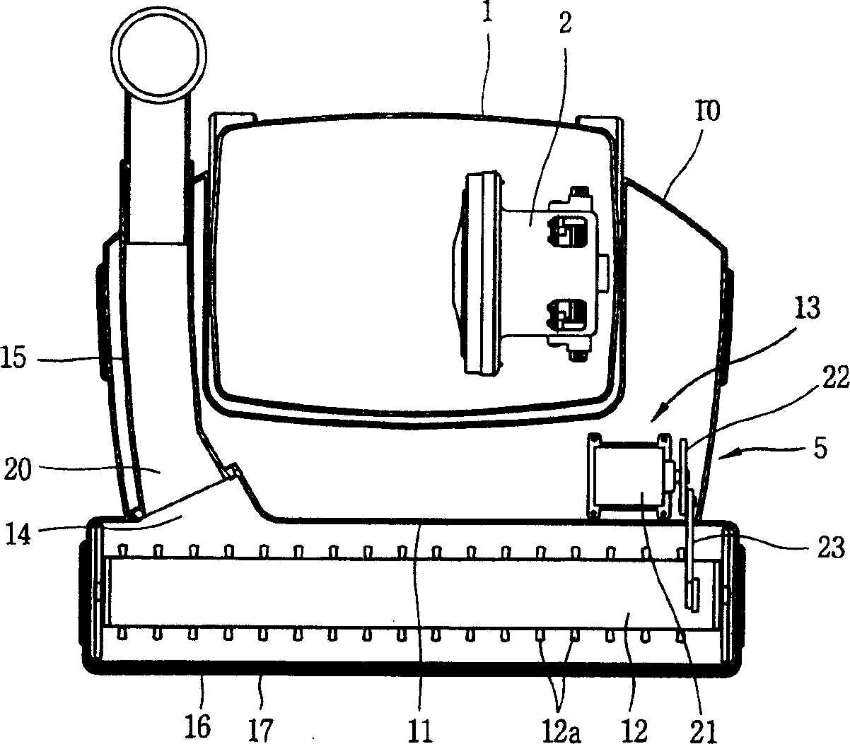
[0033] Figure 4 It is a partial cross-sectional schematic diagram of the suction head of the upright vacuum cleaner of the present invention, Figure 5 It is a longitudinal sectional view of the vacuum cleaner suction head of the present invention, Figure 6 It is a schematic view of the inner side of the suction head of the present invention.

[0034] As shown in the figure, the upright vacuum cleaner of the present invention is provided with a suction head 102, which is combined with the lower end of the chassis cover 101 arranged in the vertical direction, and installed horizontally with the floor to suck dust or foreign matter. The head 102 is arranged on the inside of the case cover 101, and is connected with the filter cover 104 under the action of the suction pipe 105. The insi...


PUM


Abstract

The invention provides a sucker header of dust collector comprising a cover of header, an inlet tube, a mouth of inlet tube, a swinging brush, a front inlet flow circuit and a back inlet flow circuit. Wherein, a plurality of guide ribs are arranged with certain space on the inner side surface of mouth of inlet tube to form a channel, for generating the suction flow from the opposite side of back inlet to the back inlet. The invention arranges the sucker of dust collector on the inner side of mouth of inlet tube and forms several channels via arranging the guide ribs in certain space to generate the flowing effect inside said channels. And the opposite side of back inlet can generate higher suction force with the increase of flowing speed to guide the sucked dust or foreign matter to the back inlet, therefore, the uniform cleaning effect can be realized.

Description

technical field [0001] The present invention relates to the suction head of the vacuum cleaner, especially the invention about the suction head of the vacuum cleaner. Compared with the rear suction port, the opposite side with relatively small suction force can also easily absorb dust, and guide these dust to the rear suction port, and finally Get the best cleaning results. Background technique [0002] Such as figure 1 , figure 2 As shown, a general upright vacuum cleaner has the following structure, that is, the case cover 1 is arranged along the upper and lower directions, and a storage space is formed inside; the fan motor 2 is accommodated inside the case cover 1 to generate suction pressure; the filter 3 is arranged on the suction part of the fan motor 2 to prevent dust from being sucked into the inside of the fan motor 2; the filter cover 4 is arranged around the filter 3 to accommodate the dust blocked by the filter 3 inside; the suction head 5, It is arranged on...

Claims


Application Information

Patent Timeline
Patent Type & Authority Applications(China)
IPC IPC(8): A47L9/04
Inventor 赵晟浩刘明根南泳硕
Owner LG ELECTRONICS (TIANJIN) APPLIANCES CO LTD
Why Eureka
Try Eureka