WLAN multi-frequency combined signal distributing system

A wireless local area network and signal distribution technology, applied in the direction of data exchange through path configuration, can solve problems such as time extension, insufficient bandwidth, poor signal-to-noise ratio, etc., and achieve the effect of high scalability

Inactive Publication Date: 2006-04-26
昂科信息技术(上海)股份有限公司
View PDF0 Cites 6 Cited by
  • Summary
  • Abstract
  • Description
  • Claims
  • Application Information

AI Technical Summary

Problems solved by technology

[0006] The main purpose of the present invention is to provide a wireless local area network (IEEE 802.11x) multi-frequency combined signal distribution system to solve the problem of wireless signal seamless coverage and near-frequency, simultaneous The contradiction between frequency interference, as well as the poor signal-to-noise ratio of the signal, low bandwidth, high bit error rate, time extension, etc.
[0007] Another object of the present invention is to provide a wireless local area network multi-frequency combination signal distribution system to solve the problem of insufficient bandwidth caused by the laying method of one channel or frequency segment corresponding to one indoor signal distribution system
[0008] Another object of the present invention is to provide a wireless local area network multi-frequency combination signal distribution system to solve the problem that a reasonable wireless network redundancy backup solution cannot be provided when multiple APs are used to cover a large-area and complex indoor environment

Method used


Image

  • WLAN multi-frequency combined signal distributing system
  • WLAN multi-frequency combined signal distributing system
  • WLAN multi-frequency combined signal distributing system

Examples


Embodiment 2

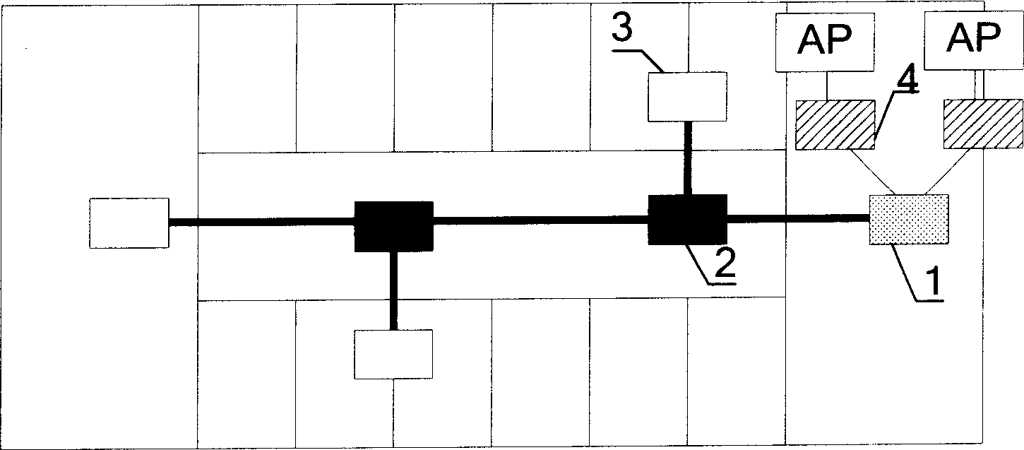
[0028] Embodiment 2: In order to further increase the coverage and strength of the signal and avoid too little power allocated to each antenna, the present invention selects a power amplifier 4 at the rear end of the AP according to the number of antennas. Such as figure 2 As shown, the APs are respectively connected to the multi-frequency combiner 1 through the power amplifier 4, so as to ensure the power requirement on the antenna and enhance the uniform coverage of the signal more effectively.

Embodiment 3

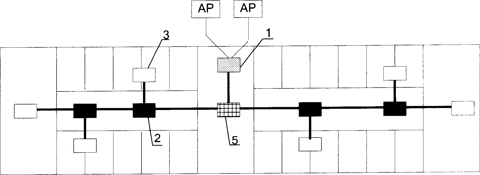
[0029] Embodiment 3: In order to multiply the signal coverage, the present invention connects a power divider 5 between the multi-frequency combiner and the cavity coupler, and divides one signal into two routes, such as image 3 As shown, the multi-frequency combiner 1 is connected to the power divider 5 through the feeder, and then the power divider 5 is respectively connected to the two-way cavity coupler 2 through the feeder, and the coupler 2 is respectively connected to the coupler 2 and the ceiling through the feeder. The antenna 3 is connected, and then the coupler 2 is connected to the antenna 3 through a feeder, and the coupler 2 is connected to the antenna 3 through a feeder.

[0030] In this way, two APs can cover the area that originally required six APs, which effectively expands the coverage area of ​​APs, reduces active devices, and facilitates unified management and maintenance of devices. In addition, the signal can be divided into three, four or even more ch...


PUM


Abstract

The invention relates to multiple frequency mixing signal distribution system in WLAN, which comprises: sends one or more AP signal to MF mixer by feed line; connecting the MF mixer into cavity coupler that links one or more antenna and / or cavity coupler. Wherein, replacing multiple AP covered traditional scheme by MF mixing signal distribution system with one set system mixing multiple AP to enhance effective bandwidth or as backup. This invention enlarges single AP signal cover range, solves same frequency interference, reduces system fault rate, realizes unified management to ensure security, and provides proper redundant backup scheme for WLAN.

Description

technical field [0001] The invention relates to a wireless local area network (WLAN) signal distribution system, in particular to a wireless local area network multi-frequency combination signal distribution system. Background technique [0002] With the rapid development of wireless local area network technology, people urgently need to solve the limitations of its frequency band allocation to meet network requirements. [0003] At present, the wireless local area network standards formulated by IEEE (International Electrical and Electronics Engineering Standards Organization) are mainly used in the market, including IEEE 802.11a, IEEE 802.11b and IEEE 802.11g. Among them, IEEE802.11b and IEEE 802.11g work in the 2.4GHz frequency band, and the frequency range is 2400MHz-2497MHz, and can be divided into 14 working channels at most. All countries in this range authorize and license the frequency range according to the actual situation. IEEE 802.11a works in the 5.8GHz freque...

Claims


Application Information

Patent Timeline
IPC IPC(8): H04L12/28
Inventor 孙东辉潘求恩陆彩莲曹华云邢军
Owner 昂科信息技术(上海)股份有限公司
Why Eureka
Try Eureka