
Blower housing and cabinet with improved blower inlet airflow distribution

A technology for blowers and cabinets, which is applied to machines/engines, components of pumping devices for elastic fluids, ventilation systems, etc., can solve the problems of blower casings obstructing installation, inability to expand blower capacity, and achieve effective air conditioning The effect of the device

Inactive Publication Date: 2010-05-26
TRANE INT INC
View PDF4 Cites 0 Cited by
  • Summary
  • Abstract
  • Description
  • Claims
  • Application Information

AI Technical Summary

Problems solved by technology

[0005] A problem faced by prior art air conditioning blowers is that the capacity of the blower cannot be expanded beyond a certain blower housing size within a given volume of cabinet because without redesigning or increasing the volume of the cabinet itself, The physical size of the increased capacity blower housing prevents it from being installed in a cabinet

Method used


Image

  • Blower housing and cabinet with improved blower inlet airflow distribution
  • Blower housing and cabinet with improved blower inlet airflow distribution
  • Blower housing and cabinet with improved blower inlet airflow distribution

Examples


Embodiment Construction

[0021] In the following description, the same components are denoted by the same reference numerals throughout the specification and drawings. For the sake of clarity and conciseness, in all instances, the figures of the drawings may not necessarily be to scale.

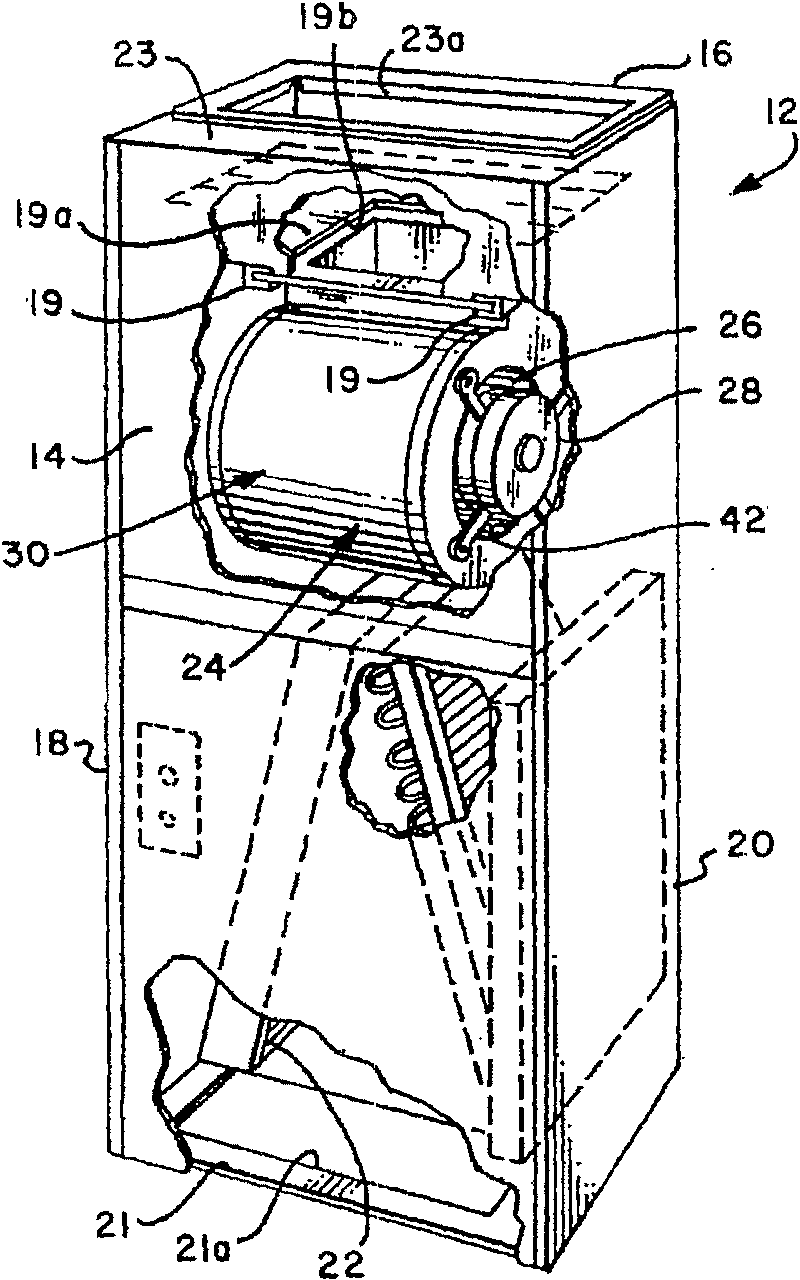
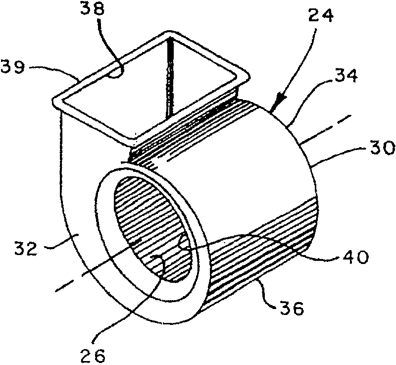
[0022] refer to figure 1 , an example of a prior art air conditioning unit for use in an HVAC system is shown, the system comprising a generally rectangular parallelepiped metal cabinet 12 having a front wall 14, a rear wall 16 and two opposing side walls 18 and 20. A bottom wall 21 may have a suitable air inlet opening 21a that allows air to enter the cabinet 12 and pass through a heat exchanger 22 such as a so-called A-frame air conditioner evaporator coil (as shown). Air is introduced into the cabinet 12 by a motor-driven centrifugal blower 24 having a conventional centrifugal impeller 26 (see figure 2 ), which is also driven by a conventional motor 28 ( figure 1 ). The air is expelled from the blower 24 int...


PUM


Abstract

An airhandling unit for an HVAC system includes a cabinet having an electric motor driven centrifugal blower disposed therein. The blower includes a scroll or volute type blower housing which may be formed of opposed releasably connectable housing parts. The blower housing parts include opposed sidewalls with axially extending compound curved portions which cooperate with an end wall which is configured to have portions which are not of substantially constant increasing radial distance from the blower impeller axis of rotation. However, a constantly increasing airflow cross-sectional flow areais provided within the blower housing for blower discharge air. The disposition of the blower housing sidewalls with respect to the cabinet walls provides improved airflow distribution for air flowing into the blower air inlet openings.

Description

[0001] Cross References to Related Applications [0002] This application is a continuation-in-part of co-pending US Patent Application Serial No. 10 / 461,042, filed June 13,2003. technical field [0003] The present invention relates to the field of blowers, and more particularly to blower housings and cabinets with improved blower inlet airflow distribution. Background technique [0004] Centrifugal air conditioning blowers are widely used to circulate air in residential and commercial heating, ventilation, and air conditioning (HVAC) systems. Motor-driven centrifugal blowers or fans mounted in volute or scroll type blower housings are particularly widely used in HVAC systems where the blower housing is mounted in a cabinet which may also contain fluids such as refrigerant fluids Heat transfer equipment such as heat exchangers or furnace heat exchangers. [0005] A problem faced by prior art air conditioning blowers is that the capacity of the blower cannot be expanded be...

Claims


Application Information

Patent Timeline
Patent Type & Authority Patents(China)
IPC IPC(8): F24F7/007F04D29/42F24F13/20F24F1/00F04D17/02F04D29/62F24F1/0053
CPCF04D29/424F04D29/626F24F7/007F24F1/0007F24F2001/004F24F1/0022F24F2013/205F04D17/02F24F1/005F24F1/0053
Inventor S·S·汉考克
Owner TRANE INT INC
Learn More