Method and device for laser marking based on liquid crystal mask tech.

A laser marking method and mask technology, applied in the field of laser marking based on liquid crystal mask technology, can solve the problems of difficult mask making, high cost, blurred graphic marks, etc., to avoid blurred marks and long service life , the effect of reducing production costs

Inactive Publication Date: 2006-04-12
JIANGSU UNIV
View PDF0 Cites 5 Cited by
  • Summary
  • Abstract
  • Description
  • Claims
  • Application Information

AI Technical Summary

Problems solved by technology

This method has high processing efficiency, but it is difficult to make a mask. When the processing line is very small, the pattern mark is blurred due to the diffraction of the laser through the mask gap, and an additional mask needs to be made when replacing the mark pattern, and the cost is high.

Method used


Image

  • Method and device for laser marking based on liquid crystal mask tech.

Examples


Embodiment Construction

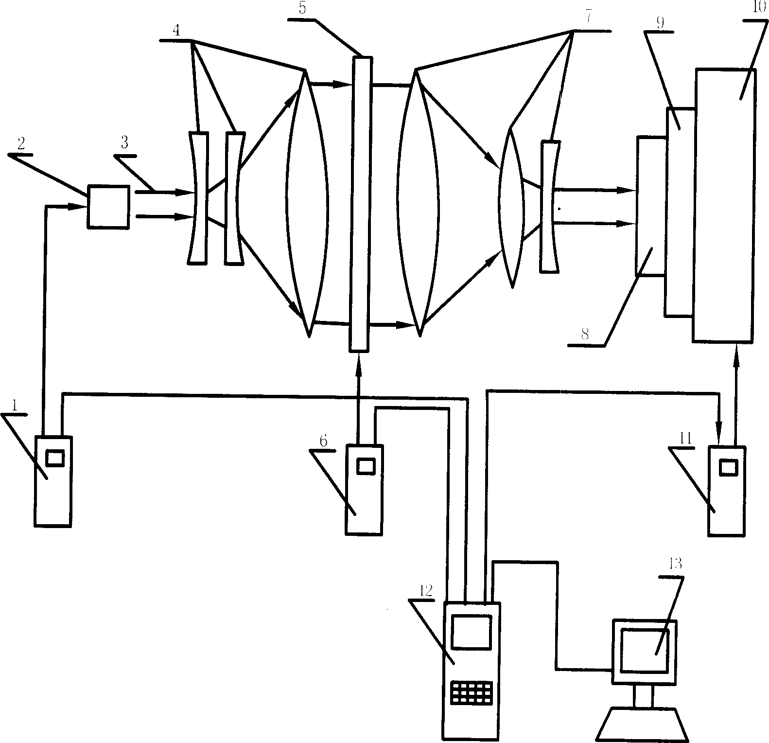
[0018] Combine below figure 1 Describe in detail the details and working conditions of the specific device proposed by the present invention.

[0019] The device for carrying out laser marking with the method of the present invention comprises a laser generator control device 1, a laser generator 2, an astigmatism system 4, a liquid crystal display screen 5 and a display screen control device 6, a focusing system 7 and a workpiece fixture system, and laser generators A digital control system 12 and a computer 13 connected to the device control device 1 , the display screen control device 6 , and the workbench control device 11 . Among them, the astigmatism system 4 is composed of a group of concave lenses and a convex lens with a large curvature; the focusing system 7 is composed of a group of convex lenses and a concave lens with a large curvature; the workpiece fixture system includes a workpiece 8, a fixture 9, a workbench 10 and a workbench control device 11 .

[0020] T...


PUM


Abstract

A method and device based on liquid crystal for preparing stereoscopic image marker on workpiece by laser is disclosed. Said device is composed of laser generator and its controller, optical diffusing system, LCD screen and its controller, focusing system, and workpiece-fixture system. Its advantage is high resolution of image marker.

Description

Technical field: [0001] The invention relates to the field of laser marking, in particular to a method and device for laser marking based on liquid crystal mask technology. It is especially suitable for printing three-dimensional graphic marks on the surface of workpieces. Background technique: [0002] Common processing laser marking technologies include point-by-point ablation and mask marking. The point-by-point ablation method uses a thin beam of laser light to irradiate the surface of the workpiece to vaporize the material to form point-shaped pits, and then moves the workpiece according to a certain trajectory to form a certain macroscopic shape of the concave mark on the surface of the workpiece. This method is less efficient and can only be used for small batch processing. Mask marking is to make a corresponding mask according to the shape of the mark, use a large-diameter laser beam to irradiate the mask, and form a hollow spot consistent with the shape of the gra...

Claims


Application Information

Patent Timeline
Patent Type & Authority Applications(China)
IPC IPC(8): B41M5/24B23K26/06B44C1/22
Inventor 张永康顾永玉葛涛张雷洪周建忠冯爱新
Owner JIANGSU UNIV
Why Eureka
Try Eureka