Method for realizing dynamic layout of high-performance server based on group structure
A dynamic deployment and server technology, applied in multi-programming devices, digital transmission systems, electrical components, etc.
- Summary
- Abstract
- Description
- Claims
- Application Information
AI Technical Summary
Problems solved by technology
Method used
Image
Examples
Embodiment 1
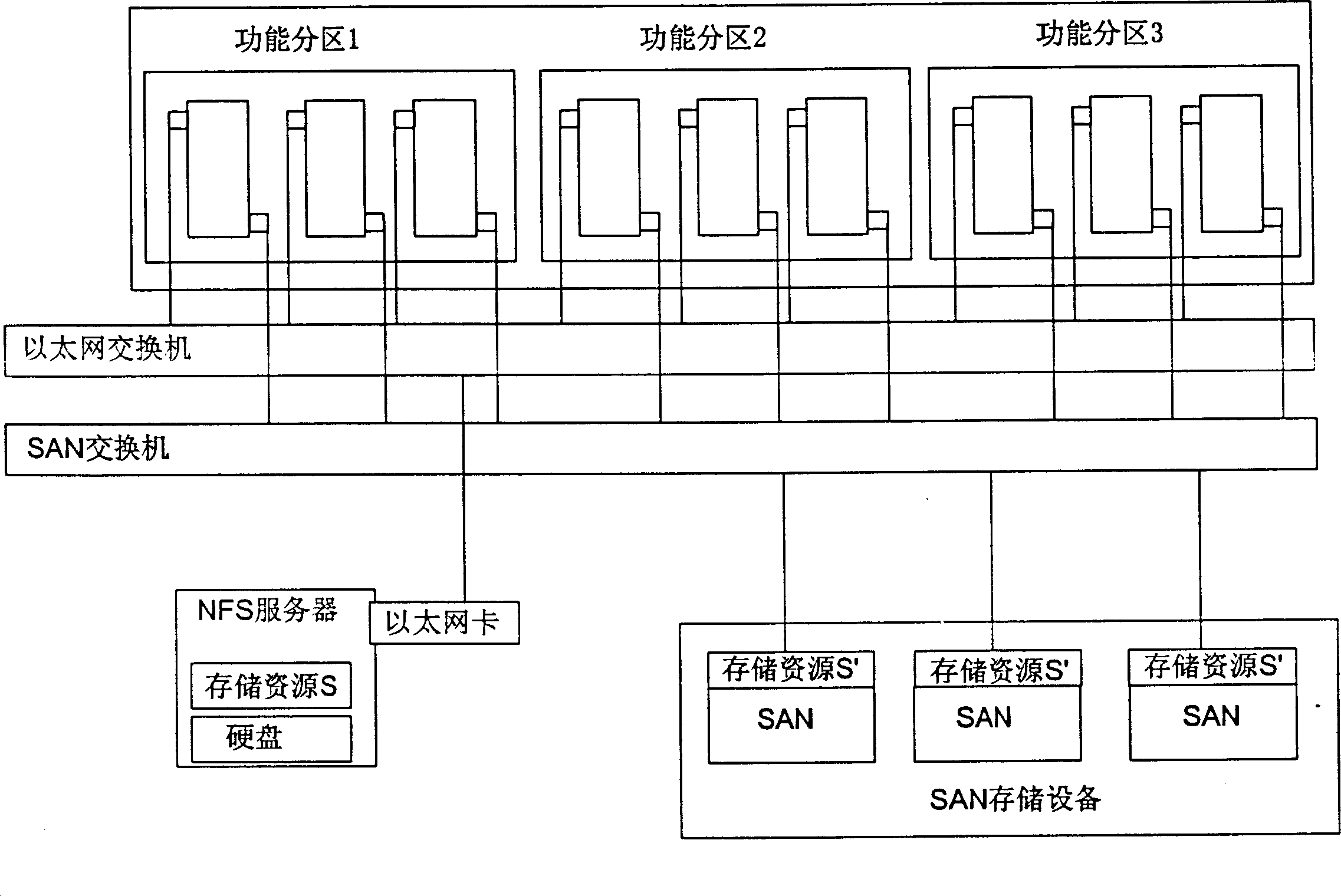
[0028] Such as figure 2 As shown; the cluster supports three types of applications, and the nodes used run in functional partitions 1, 2, and 3 respectively. Assume that the current workload in functional partition 1 is very heavy, while the workload in functional partition 2 is light. Dynamically deployed Proceed as follows:
[0029] 1. Monitor the new computing resources in the newly added cluster as backup computing resources;
[0030] 2. Monitor the workload of nodes in each functional partition in the cluster, and assign nodes with lighter workloads
[0031] 3. As a backup computing resource;
[0032] 4. It is possible to extract a certain computing node in functional partition 2, such as C2;
[0033] 5. Dynamically bind image S1 required by functional partition 1 for C2;
[0034] 6. C2 guides and executes the image S1, and builds a new computing node C’ that supports functional partition 1;
[0035] 7. Add C' to functional partition 1 to increase the computing powe...
Embodiment 2
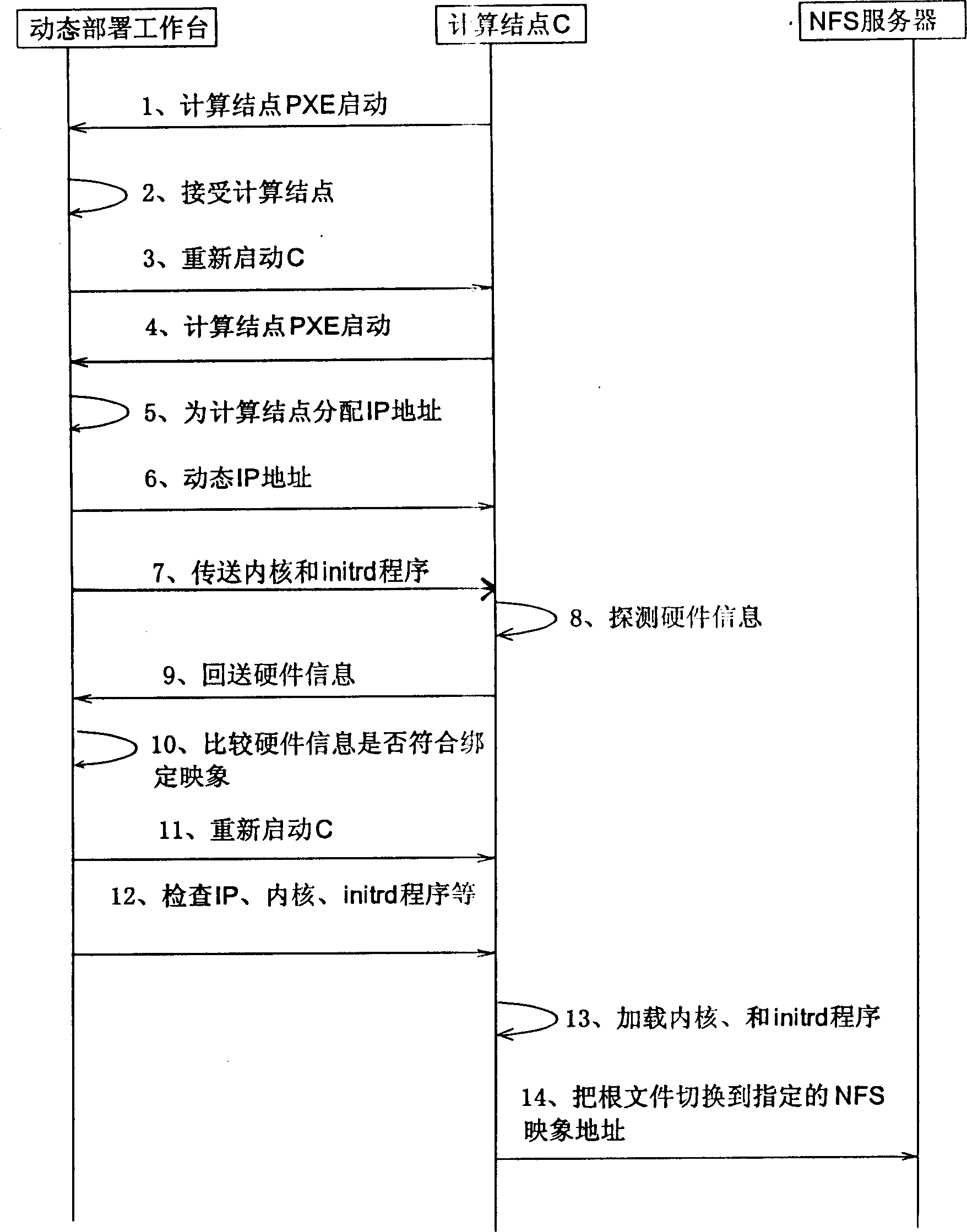
[0039] image 3 What is shown is a dynamic deployment console, which controls the interactive process of the console, computing nodes, and NFS server during the process of starting a node newly added to the cluster from the image on the NFS server. It can be seen that if the computing node only uses the image on the NFS server to build a new computing node, there is no need for SAN equipment, which can save the investment in expensive SAN equipment. It's just that the NFS server as a centralized storage will bring IO access bottlenecks, so the method for computing nodes to use the storage image on the NFS server to build nodes can be regarded as a cheap solution with low performance requirements.
[0040] image 3 Steps 1-14 except steps 4-10 are the same as the process of establishing a diskless workstation based on NFS, PXE, and tftp tools. The purpose of steps 4-10 is to check whether the computing resources match the bound image resources to prevent The difference caused...
Embodiment 3
[0042] Such as Figure 4As shown, in the process of using a dynamic deployment console to control a node newly added to the cluster to start from the image on the SAN, the key is to use the two-stage boot process provided by the operating system itself. In the first stage, use the boot of the Ethernet card Function, guide the kernel of the operating system and load the driver program of the memory card on the Ethernet (steps 12 and 13); in the second chicken stage, the memory card without the network boot function is identified after the operating system startup stage is over and before the root file system is switched Take out the storage device, and switch the root file system to the identified SAN (step 14). Although this node is booted on a low-speed Ethernet, it can use a high-speed network during operation (such as infiniband, fiber channel network) For high-speed communication and network storage.
[0043] It can be seen from the above-mentioned embodiments that the dy...
PUM
 Abstract
Description
Claims
Application Information
 - Generate Ideas
- Intellectual Property
- Life Sciences
- Materials
- Tech Scout
- Unparalleled Data Quality
- Higher Quality Content
- 60% Fewer Hallucinations
Browse by: Latest US Patents, China's latest patents, Technical Efficacy Thesaurus, Application Domain, Technology Topic, Popular Technical Reports.
© 2025 PatSnap. All rights reserved.Legal|Privacy policy|Modern Slavery Act Transparency Statement|Sitemap|About US| Contact US: help@patsnap.com


