Pressure resistance large overloading accelerometer and preducing method thereof

An accelerometer and large overload technology, applied in the field of microelectronics, can solve the problems of incompatibility of integrated circuit technology, poor sensitivity of large overload accelerometers, etc., and achieve the effect of easy anti-high overload structure, simple structure and good impact resistance

Inactive Publication Date: 2006-03-01
北京青鸟元芯微系统科技有限责任公司
View PDF0 Cites 15 Cited by
  • Summary
  • Abstract
  • Description
  • Claims
  • Application Information

AI Technical Summary

Problems solved by technology

[0003] The purpose of the invention is to solve the problem of poor sensitivity of existing large overload accelerometers and incompatibility with integrated circuit technology

Method used


Image

  • Pressure resistance large overloading accelerometer and preducing method thereof
  • Pressure resistance large overloading accelerometer and preducing method thereof
  • Pressure resistance large overloading accelerometer and preducing method thereof

Examples


Embodiment Construction

[0026] DETAILED DESCRIPTION OF THE PREFERRED EMBODIMENTS The preferred embodiments of the present invention will be described in more detail below with reference to the accompanying drawings of the present invention.

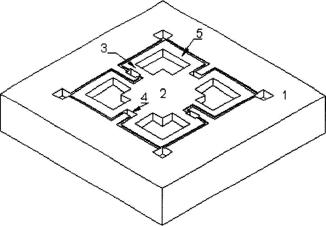
[0027] figure 1 Shown is a structural schematic diagram of the accelerometer of the present invention, the whole structure includes a sensitive mass, four beams, piezoresistors on the beams, metal wiring and welding points, and a silicon substrate.

[0028] The functions and connections of each part are as follows:

[0029] 1) Sensitive mass 2, when the accelerometer is subjected to an impact in a sensitive direction, the inertia of the mass 2 will cause displacement and deformation of the mass 2 relative to the silicon substrate 1 .

[0030] 2) Four crossbeams 3, the crossbeams 3 are used as the supporting arms of the mass block 2, and at the same time as the preparation area of ​​the piezoresistor. When the impact occurs, the mass block 2 pulls the beam 3 to...


PUM


Abstract

The present invention provides a piezoresistive large-overload accelerometer. It is made up by adopting Si base MEMS technique. Said invention also provides the concrete steps of its preparation method. It can convert mechanical impact signal into electric signal, after the output signal is undergone the processes of amplification and temperature compensation, it can be used for calibrating acceleration extent.

Description

technical field [0001] The invention belongs to the technical field of microelectronics, and in particular relates to a piezoresistive inertial sensor used for measuring large overload acceleration (1000g-100000g) in a microelectromechanical system. Background technique [0002] It is difficult to make accelerometers resistant to large overload by using traditional devices. Most of the methods currently used are to use SiC materials to make such devices by using micro-electromechanical system processing methods, and deposit SiC materials on silicon substrates to form composite films. structure, the piezoresistor is formed by implanting impurity ions into SiC, and then the Si substrate on the back of the SiC film is etched away by back etching. Using the piezoresistive properties of the SiC material, when there is an external impact, the SiC film due to inertia The deformation occurs, so that the stress distribution on the surface changes, and the piezoresistive resistance va...

Claims


Application Information

Patent Timeline
IPC IPC(8): G01P15/12
Inventor 张威石进杰郝一龙李婷张大成王阳元
Owner 北京青鸟元芯微系统科技有限责任公司
Why Eureka
Try Eureka