Combined wind energy and hydraulic power varying generator

A power generation equipment and variable power technology, which is applied in wind power generation, mechanical equipment, wind engines, etc., can solve the problems of increased manufacturing costs, difficulties in transportation, erection, monitoring, and maintenance, restrictions on the development and utilization of green and environmentally friendly wind energy, manufacturing costs and Problems such as high equipment installation cost, etc., to achieve the effect of easy erection and maintenance, material saving, and manufacturing cost reduction

Inactive Publication Date: 2006-03-01
柳海源
View PDF0 Cites 6 Cited by
  • Summary
  • Abstract
  • Description
  • Claims
  • Application Information

AI Technical Summary

Problems solved by technology

[0003] 1. Since most of the current wind power generation equipment weighs several tons, all of which are erected on columns with a height of 30 meters to 60 meters, the requirements for the strength, rigidity, stability and safety of the columns are extremely high, which increases the manufacturing cost, Difficulty in transportation, erection, monitoring and maintenance
[0004] 2. Due to the erratic and random wind energy in nature, the adjustment requirements for constant-speed power generation of generators are very strict, the design of the speed control device is very complicated, and the precision requirements are extremely high, which increases the manufacturing and production costs.
Due to the high cost of manufacturing and equipment installation, the on-grid electricity price of wind power is as high as 0.9 yuan / kwh, which is much higher than the on-grid electricity price of thermal power. National policy support and subsidies are still needed to solve the overpriced part of the on-grid electricity, which affects the government and enterprises. Enthusiasm and enthusiasm for wind power, slow investment and development, have restricted the development and utilization of renewable, green, and zero-pollution wind energy in my country, and affected the rapid development of wind power in China

Method used


Image

  • Combined wind energy and hydraulic power varying generator

Examples


Embodiment Construction

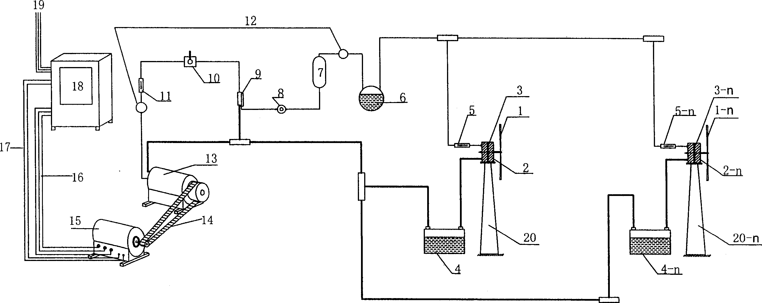
[0028]The newly developed 4 MW combined wind energy hydraulic variable power generation equipment, the maximum output power of the generator 15 is 4000kw×120%=4800kw, and the diameter of a single wind wheel is 180 meters, and four wind wheels 1 with a radius of 40 meters are now used. , drives the corresponding four high-power oil pumps 3 to work, and the output of the oil pump 3 is connected to the transmission 13 through the one-way valve 5, the pressure accumulator 6, the pressure collecting cylinder 7, and the pressure regulator 8 to provide high-pressure oil pressure for the transmission 13 , the transmission machine 13 converts the hydraulic transmission into a required constant mechanical speed output through several translational hydraulic cylinders, and then drives the generator 15 through the transmission 14 to generate three-phase alternating current. When the wind force decreased and the wind energy decreased, the hydraulic transmission power decreased. Now, the com...


PUM


Abstract

The wind energy hydraulic power varying generator is one wind force power generator to convert wind energy into hydraulic energy to drive great power generator to produce electric power. The structural principle of the present invention is that the kinetic energy of several wind wheels are combined and converted into hydraulic energy mechanically, and the hydraulic energy is integrated into one powerful hydraulic transmission mechanism and used in driving one great power generator. The present invention has computer control to regulate hydraulic transmission and to stabilize rotation speed, and generator with varying power to output voltage. The present invention has simple structure, easy manufacture, low cost and great electrical power.

Description

1. Technical field: [0001] The invention relates to a wind power generating equipment which converts wind energy into hydraulic energy in a combined form to provide kinetic energy for a generator, and then drives a high-power generator to generate electricity. Two background technologies: [0002] The current wind power generation equipment is that the wind wheel rotates through the variable speed and the adjustment device directly drives the generator to generate electricity. The following problems exist in long-term operation: [0003] 1. Since most of the current wind power generation equipment weighs several tons, all of which are erected on columns with a height of 30 meters to 60 meters, the requirements for the strength, rigidity, stability and safety of the columns are extremely high, which increases the manufacturing cost, The difficulty of transportation, erection, monitoring and maintenance. [0004] 2. Due to the erratic and random nature of the wind energy, the...

Claims


Application Information

Patent Timeline
IPC IPC(8): F03D9/02F03D7/04F03D9/25
CPCY02E10/723Y02E60/16Y02E10/72Y02P70/50
Inventor 柳海源柳超
Owner 柳海源
Why Eureka
Try Eureka