Eureka AIR delivers breakthrough ideas for toughest innovation challenges, trusted by R&D personnel around the world.

Three-dimensional printing formation unit and method

A molding equipment and three-dimensional printing technology, applied in special data processing applications, instruments, electrical digital data processing, etc., can solve the problems of complex parts production and low material utilization rate, and achieve simple parts production, high material utilization rate, post-production Handle simple effects

Inactive Publication Date: 2006-03-01
SHANGHAI UNIVERSITY OF ELECTRIC POWER
View PDF5 Cites 71 Cited by
  • Summary
  • Abstract
  • Description
  • Claims
  • Application Information

AI Technical Summary

Problems solved by technology

[0003] The above three-dimensional printing molding methods require a specially designed support structure. For parts with complex internal structures, the production is complicated and the material utilization rate is low.

Method used


Image

  • Three-dimensional printing formation unit and method
  • Three-dimensional printing formation unit and method
  • Three-dimensional printing formation unit and method

Examples


Embodiment 1

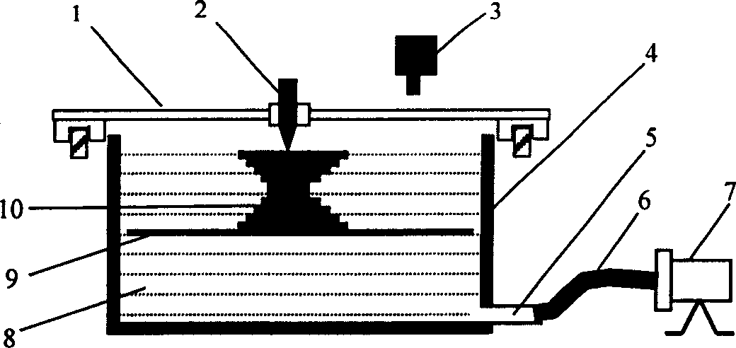
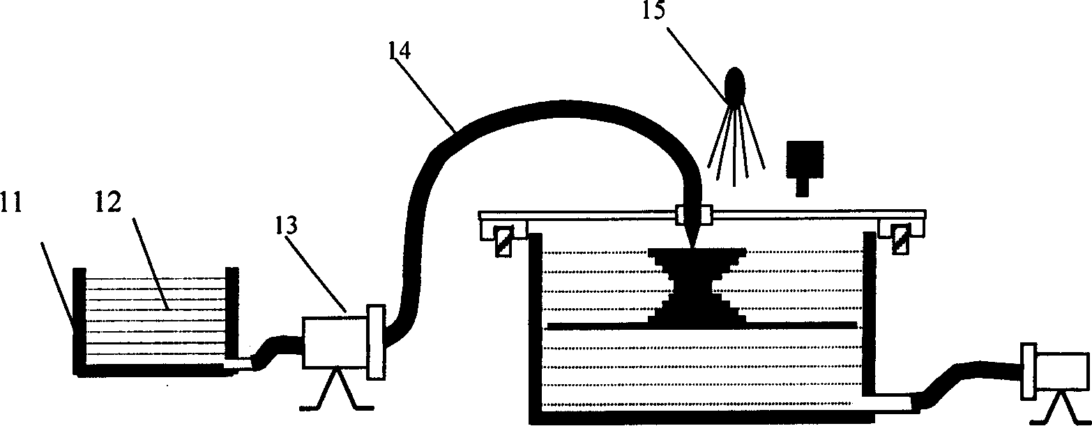
[0042] This embodiment adopts as figure 2 In the shown device of the present invention, liquid photosensitive resin 12 is selected as the molding material, and liquid epoxy resin is used as the support material 8 . The photosensitive resin storage 12 is stored in the raw material tank 11, and the photosensitive resin 12 is transported to the nozzle 2 through the conduit 14 and the pump 13. The photosensitive resin 12 ejected from the nozzle 2 is irradiated by the ultraviolet lamp 15, and the liquid photosensitive resin 12 is cured.

[0043] The processing process is as follows:

[0044] 1. The 3D CAD model data is processed by computer and divided into a series of cross-sectional graphics with a certain thickness.

[0045] 2. The lifting platform 9 is lifted to a certain height, and the liquid level sensor is used to detect the height of the liquid level 3. According to the detected liquid level height, the support material epoxy in the liquid storage tank 4 is changed throu...

Embodiment 2

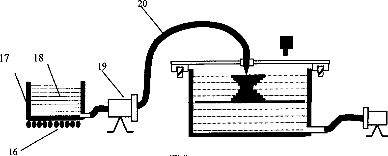
[0054] This embodiment adopts as image 3 In the shown device of the present invention, wax 18 is selected as the molding material, and liquid epoxy resin is used as the support material 8 . The wax 18 is stored in the raw material tank 17, heated to a molten state by the heating plate 16, and the molten wax is transported to the nozzle through the conduit 20 and the pump 19, and the molten wax ejected from the nozzle is cooled and solidified.

[0055] The processing process is as follows:

[0056] 1. The 3D CAD model data is processed by computer and divided into a series of cross-sectional graphics with a certain thickness.

[0057] 2. The heating plate 16 heats the raw material tank 17 to melt the solid wax and keep it at a stable temperature of 70-100°C.

[0058] 3. The lifting platform 9 is lifted to a certain height, and the liquid level sensor is used to detect the height of the liquid level 3. According to the detected liquid level height, the support material epoxy ...


PUM


Abstract

The three-dimensional printing formation unit includes one X-Y work bench and one elevating platform. The X-Y work bench has lower liquid tank with bottom liquid support medium, and upper nozzle with downward spout, over liquid level sensor. The lower liquid tank has liquid support material and bottom flow guide hole, the elevating platform is located inside the liquid support material, and the flow guide hole is connected via duct with pump. The three-dimensional printing formation method includes spraying the forming material via the nozzle, forming on the liquid support material surface and based on the cross section data, curing the forming material on the surface of the support material to form one layer of the part, lowering the work bench for one layer of thickness for the painting of the next layer, and adhering the adjacent layer to form three-dimensional body. The present invention has the advantages of no need of special support structure, simple part making process, high material utilization, etc.

Description

technical field [0001] This patent relates to a three-dimensional rapid prototyping device and method, especially a three-dimensional printing forming device and its use method. Background technique [0002] At present, there are many types of rapid prototyping equipment, including Stereolithography-SL, Fused Deposition Modeling-FDM, Laminated Object Manufacturing-LOM, Selective Laser Sintering- SLS) and three-dimensional printing (3Dimensional Printing-3DP), etc. The patented technology related to 3D printing mainly includes US Patent No. 5387380 (applicant Cima) in February 1995. By selectively spraying the binder on the surface of the powder material, the powder material in the cross section of the part is bonded together, so layer by layer Bonding molding, after the bonding is completed, the unbonded powder material is taken out to obtain a molded part. The printing method of U.S. Patent 5,878,664 (applicant Hartka) in March 1999 is to use the pr...

Claims


Application Information

Patent Timeline
Patent Type & Authority Applications(China)
IPC IPC(8): B29C67/00B29C41/00G06F17/50
Inventor 吴懋亮周宏志徐伟虹任建兴张浩
Owner SHANGHAI UNIVERSITY OF ELECTRIC POWER
Why Eureka
Eureka Blog
Learn More