Vision contraposition device for mobile component

A technology of visual alignment and moving parts, applied in the direction of electrical components, electrical components, etc., can solve problems such as the need to stop or strictly control, measurement and installation cannot be carried out at the same time, and reduce positioning accuracy, etc., to achieve a simple and fast alignment process of parts installation, Effects of cost reduction and structural complexity reduction

Inactive Publication Date: 2006-02-22
HUAZHONG UNIV OF SCI & TECH
View PDF3 Cites 14 Cited by
  • Summary
  • Abstract
  • Description
  • Claims
  • Application Information

AI Technical Summary

Problems solved by technology

However, this patent application has the following problems: 1. The imaging after two reflections can only be realized at a certain point when the part passes over, so it is necessary to stop or strictly control the synchronization of the movement mechanism and camera exposure; 2. The camera and the suction head are parallel Vertically downward, and there is a certain distance, so for the same installation position, the measurement of the camera and the installation of the pick-up head cannot be carried out at the same time. When the camera is positioned and then the pick-up head is moved to align, the movement error of the motion system will reduce the positioning precision

Method used


Image

  • Vision contraposition device for mobile component
  • Vision contraposition device for mobile component
  • Vision contraposition device for mobile component

Examples


Embodiment Construction

[0018] The technical solution of the present invention will be further described below in conjunction with the accompanying drawings.

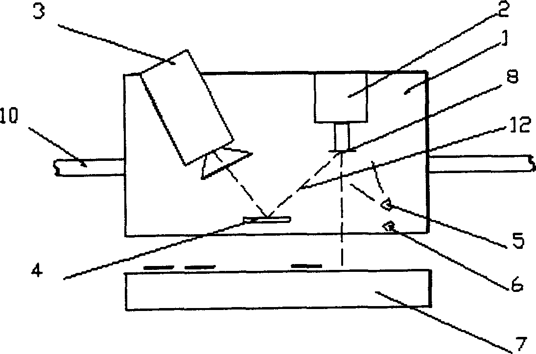
[0019] figure 1It is a structural schematic diagram of the present invention, a pick-up head 2, an electronic camera 3, a half-mirror 4, a reflective imaging light source 5 acting on the bottom of the component 8 and a transmission imaging light source acting on the installation position 9 are fixed on the pick-up mechanism platform 1 6. The pick-up mechanism platform 1 can move along the X-Y plane on the plane of the work platform 7, and only the X-axis guide rail 10 is shown in the figure; the pick-up head 2 faces the work platform 7 and can move along the Z-axis direction perpendicular to the X-Y plane of the work platform 7 . The visual system adopts visible light imaging, and the electronic camera 3 can adopt an industrial CCD or COMS camera, and the exposure can be controlled through an optical lens or a camera. / 2. The position of t...


PUM


Abstract

Disclosed a visual positioning device of moving component belongs to the automatic detecting device in the productive process of electro-mechanic product, which can reduce the design complexity of system and improve the operational efficiency of device. The invention mounts a pick-up head, a electron camera, a semi-transparent mirror and a lighting source on the pick-up device workbench. Wherein, the semi-transparent mirror is mounted between the electron camera and the pick-up head; the electron camera is mounted in a certain inclined angle to make the pick-up head picks up the bottom picture of element to be reflected by semi-transparent mirror to imaged clearly in the electron camera; the projected position of pick-up head on the workbench can be imaged clearly via the semi-transparent mirror. The invention realizes the detection, the displacement adjustment of pick-up element, and the same operation on the mounting position can be synchronously operated with the transfer and mounting detected by one visual system in the transferring process of mounting elements; and the pick-up and the assembling operations on the pick-up device are not need additive process to make the mounting-positioning process more simply and fast.

Description

technical field [0001] The invention belongs to an automatic detection device in the production process of electromechanical products, in particular to a visual alignment device. It is mainly used in the assembly and packaging of mechanical and electrical products in the automatic production process, and realizes the accurate alignment of assembly in automatic production. Background technique [0002] In the automatic assembly process of electromechanical products, a set of automatic or mechanical picking mechanisms are usually used to pick up resistors, capacitors, integrated circuits, chips and other components from the supply place, and transfer them to the installation position to complete the alignment installation. When a component is picked, its positional relationship may be uncertain, so it is necessary to obtain the position information of the picked installed component. When the pick-up mechanism transfers the components to the installation position according to ...

Claims


Application Information

Patent Timeline
Patent Type & Authority Applications(China)
IPC IPC(8): H05K13/08H05K13/04
Inventor 王瑜辉尹周平熊有伦
Owner HUAZHONG UNIV OF SCI & TECH
Why Eureka
Try Eureka