Roller scraping cutter

A scraper and roller technology, used in glass manufacturing equipment, glass cutting devices, glass production, etc., can solve the problems of roller scraper slippage, weakening the effect of vibration impact, unable to obtain vibration impact, etc., achieving beautiful incisions and minimal formation of horizontal cracks the effect of

Inactive Publication Date: 2006-02-22
MJ TECH
View PDF0 Cites 9 Cited by
  • Summary
  • Abstract
  • Description
  • Claims
  • Application Information

AI Technical Summary

Problems solved by technology

[0013] However, in the former invention, through the peripheral edge ( image 3 Concave-convex patterns are formed on the part of 23) to increase the vibration frequency of each rotation, and limit the height of the protrusion 24 to weaken the vibration impact effect, so vertical cracks of sufficient depth cannot be formed
In addition, in order to generate a large vibration impact, the concave-convex pattern of the protrusions 24 is enlarged, that is, the protrusions 24 with a large height H and a pitch P are formed, but at this time, the rotation of the roller scraper is likely to cause slippage.
In addition, when producing hobs, it is complicated to process the above-mentioned concave-convex patterns on the outer periphery.
[0014] In addition, the latter's patented technology, the mounting hole ( Figure 4 32) The shape is more than a quadrangular polygon, and when rotating, the vibration amplitude in the vertical direction is narrow, which cannot produce sufficient vibration shock
In addition, since no polygonal portion is formed inside the mounting hole 32, sufficient vibration cannot be obtained every time one rotation is made.
[0015] On the other hand, in order to obtain sufficient vibration when rotating one circle at a time, it is necessary to form the mounting hole 32 into a polygon with multiple sides, but at this time the vibration amplitude is narrow, and sufficient vibration shock cannot be obtained.

Method used


Image

  • Roller scraping cutter
  • Roller scraping cutter
  • Roller scraping cutter

Examples


Embodiment Construction

[0028] The present invention will be described in detail below with reference to the accompanying drawings.

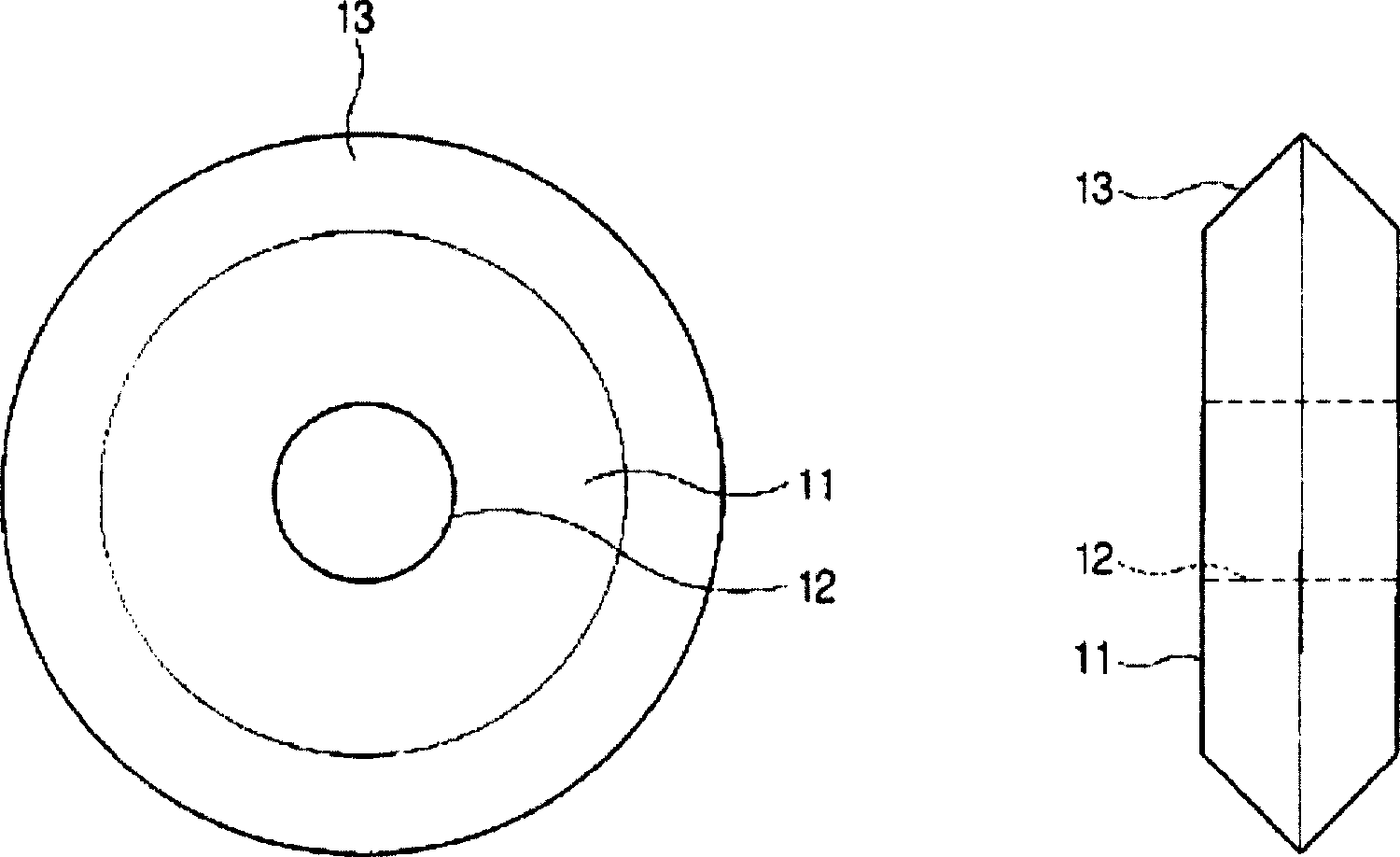
[0029] Such as Figure 5a and Figure 5b As shown, one embodiment of the roller scraper of the present invention is composed of a main body 111 having a shaft hole 112 at the center, and a cutting portion 113 having a V-shaped section at the outer periphery of the main body 111 .

[0030] The shaft hole 112 has a larger diameter than the aforementioned shaft so that a shaft (not shown) is inserted into the shaft hole 112 and fitted.

[0031] The cutting portion 113 has 18 outer peripheral notches 114 formed at equal angular intervals along the outer periphery. Here, the outer peripheral notch 114 is formed in a radial direction perpendicular to the circumferential direction on the outer periphery. This is for easy processing of the outer peripheral notch 114 .

[0032] In the shaft hole 112 part of the main body 111, six inner peripheral grooves 115 parallel to the...


PUM


Abstract

The invention relates to a scribing wheel cutter used for scribing a brittle material such as a glass plate or the like. The scribing wheel cutter consists of a main body part in which an axis hole is formed in a central part and a cutting part with a cross section of V form formed on an outer peripheral edge of the main body part. The cutter involves many numbers of a peripheral edge notch formed at a regular angle interval along the peripheral edge of the cutting part and many numbers of an inner circumference groove formed along an inner peripheral edge of the axis hole and being parallel to the axis line less numbers than those of the outer peripheral edge notches. A smooth cutting face after a cutting is obtained by reducing a shear force required for cutting of a product and minimizing the generation of horizontal cracks because perpendicular cracks can be deeply formed on the surface of glass being an object of the scribing in the method.

Description

technical field [0001] The present invention relates to a scribing wheel cutter, and more particularly to a scribing wheel cutter that enables easy cutting of products by forming deep vertical cracks on a target surface such as a glass plate. Background technique [0002] The roller scraper is a tool for cutting brittle materials such as glass plates. With this cutting tool, a fracture line (scribing) is drawn on the surface of the cutting target to form a crack of a specified depth (called a "vertical crack") . Then, shearing force is applied on both sides of the cutting line, and the vertical crack is extended to the opposite side surface of the cutting target, thereby cutting the product. [0003] Such as figure 1 As shown, the conventional roller scraper is disc-shaped, which includes a main body 11 having a circular shaft hole 12 in the center, and a cutting portion (cutting) 13 having a V-shaped cross section on the outer periphery of the main body. [0004] The mat...

Claims


Application Information

Patent Timeline
Patent Type & Authority Applications(China)
IPC IPC(8): C03B33/02
CPCC03B33/027C03B33/033C03B33/037C03B33/10Y02P40/57
Inventor 金信郁
Owner MJ TECH
Why Eureka
Try Eureka