
Multi-channel harmonic wave restraining device

A harmonic suppression and multi-channel technology, applied in harmonic reduction devices, AC networks to reduce harmonics/ripples, etc., can solve the problems of large volume and weight, limitations, complexity and high cost, and achieve harmonic suppression current, easy maintenance and simple structure

Inactive Publication Date: 2006-02-15
HUAZHONG UNIV OF SCI & TECH
View PDF1 Cites 6 Cited by
  • Summary
  • Abstract
  • Description
  • Claims
  • Application Information

AI Technical Summary

Problems solved by technology

This device has the following disadvantages: (1) Since this converter has only one secondary fundamental winding, that is, there is only one branch circuit to form a series resonant circuit of the secondary fundamental winding, inductance coil, and capacitor, so that it can be connected with the primary fundamental current Ampere-turn balance, when the primary side current is very large, the secondary side current will also be very large, because the power of the inductance coil and capacitor is large, the price is high, the volume and weight are also large, and the application is limited
(2) The active filtering method composed of detection iron core, detection winding, operational amplifier, driver and harmonic winding is adopted to further offset the residual harmonic current. Since the proportion of residual harmonic current is not large, the detection iron Core, detection windings, operational amplifiers, drivers, and harmonic windings constitute an active filtering method, which has high complexity and cost, reduced reliability, and uneconomical input-output ratio.

Method used


Image

  • Multi-channel harmonic wave restraining device

Examples


Embodiment Construction

[0008] The present invention is further described now in conjunction with accompanying drawing.

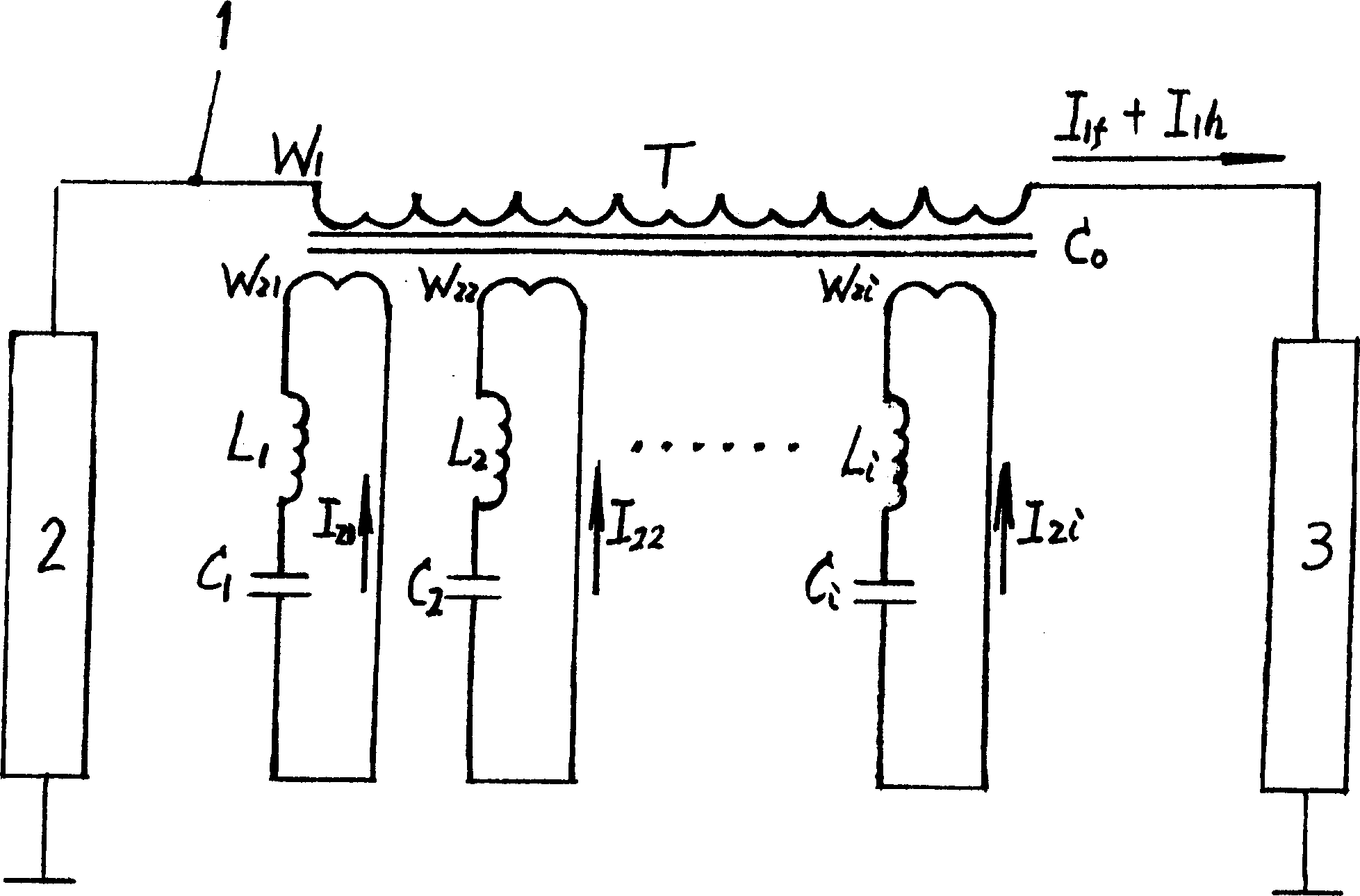
[0009] figure 1 A schematic circuit diagram of the present invention is given. The primary winding W of the converter T 1 Connected in series on the grid bus 1, one end of the grid bus is connected to the grid 2, and the other end is connected to the harmonic source load 3; the i secondary windings W of the converter T 21 , W 22 ...W 21 The number is the same, the geometric size is equal, and each winding is connected with the corresponding inductance coil and capacitor L 1 、C 1 , L 2 C 2 ...... L i 、C 1 connected in series to form an inductance and capacitance series resonant circuit of i channels.

[0010] The main iron core C of the converter T 0 It can be a ring-shaped iron core wound by strip-shaped cold-rolled silicon steel sheets, or a rectangular iron core formed by stacking sheet-shaped cold-rolled silicon steel sheets.

[0011] After the multi-channel harmoni...


PUM


Abstract

The multichannel harmonic suppressor with inductance coil and capacitor of low voltage and power belongs to power network control device and overcomes the shortcoming in existing technique to decrease cost and volume and satisfy require for high voltage and current. Wherein, joining the product in series with power network bus-bar, arranging i winding coils on sub converter connected to inductance coil and capacitor in series to constitute series resonant circuit of inductance and capacitor, wherein, it should be ªÏL=1 / ªÏC for working frequency ªÏ; all the inductance value and capacitor value equals, so does the number of turns and geometric size. This invention is convenient to maintenance.

Description

technical field [0001] The invention belongs to electric network control equipment in the electrical technology, and particularly relates to a high-power harmonic suppression device, which is used for suppressing the harmonic current generated by high-power nonlinear loads. Background technique [0002] The Chinese invention patent application "harmonic suppression device" with application number 02139029.0 is to form a series resonant circuit for the fundamental wave through the secondary fundamental winding, inductance coil and capacitor of the converter to realize the primary and secondary harmonics of the converter. The fundamental ampere-turn balance between them makes the converter present low impedance to the primary fundamental current and high impedance to the harmonic current, allowing the fundamental current to pass smoothly and effectively suppressing most of the harmonic current. For the remaining part of the first harmonic current, the active filtering composed...

Claims


Application Information

Patent Timeline
IPC IPC(8): H02J3/01
CPCY02E40/40
Inventor 任士焱
Owner HUAZHONG UNIV OF SCI & TECH
Learn More