Transmission gear

A transmission device and rotating shaft technology, applied in transmission devices, fluid transmission devices, control devices, etc., can solve the problems of large-scale transmission devices, complex working oil passages, and large working oil circulation resistance, and improve transmission efficiency and performance. The effect of improving and suppressing the flow resistance

Inactive Publication Date: 2006-02-08
HONDA MOTOR CO LTD
View PDF1 Cites 5 Cited by
  • Summary
  • Abstract
  • Description
  • Claims
  • Application Information

AI Technical Summary

Problems solved by technology

Therefore, the hydraulic oil flow direction is changed by 90 degrees from the supply oil passage to the torque converter side, and the flow direction is changed by 90 degrees from the torque converter to the discharge oil passage, and the flow resistance

Method used


Image

  • Transmission gear
  • Transmission gear
  • Transmission gear

Examples


Embodiment Construction

[0016] Next, an embodiment of the present invention will be described based on an embodiment of the present invention shown in the drawings.

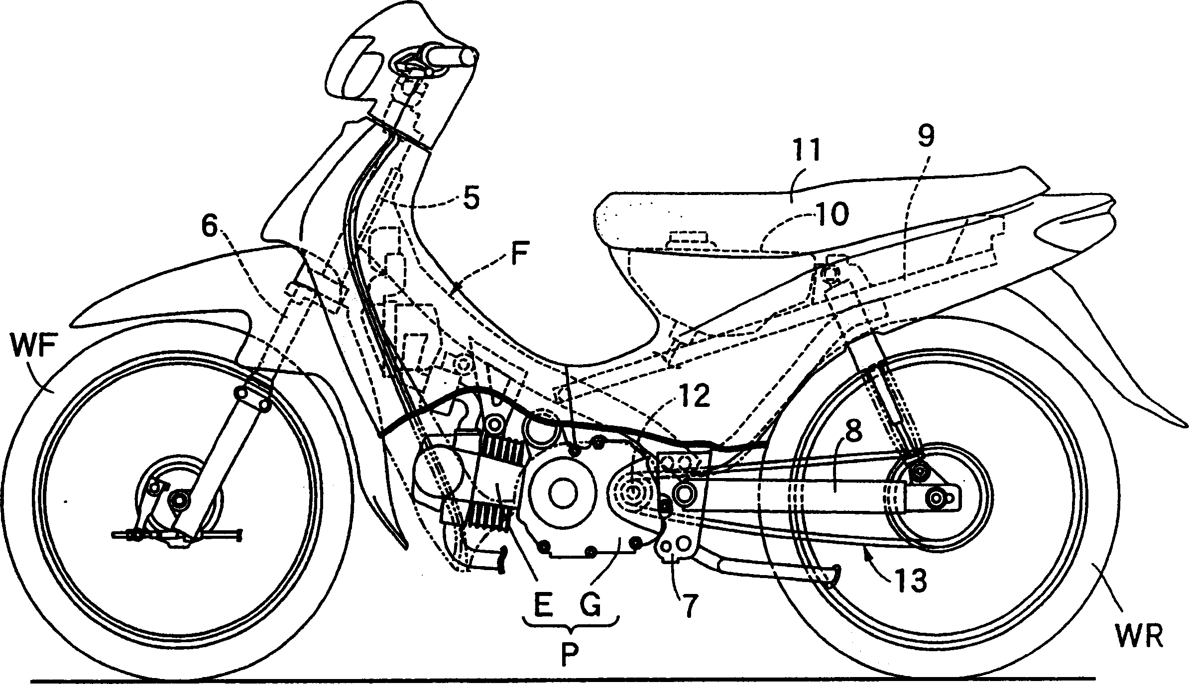
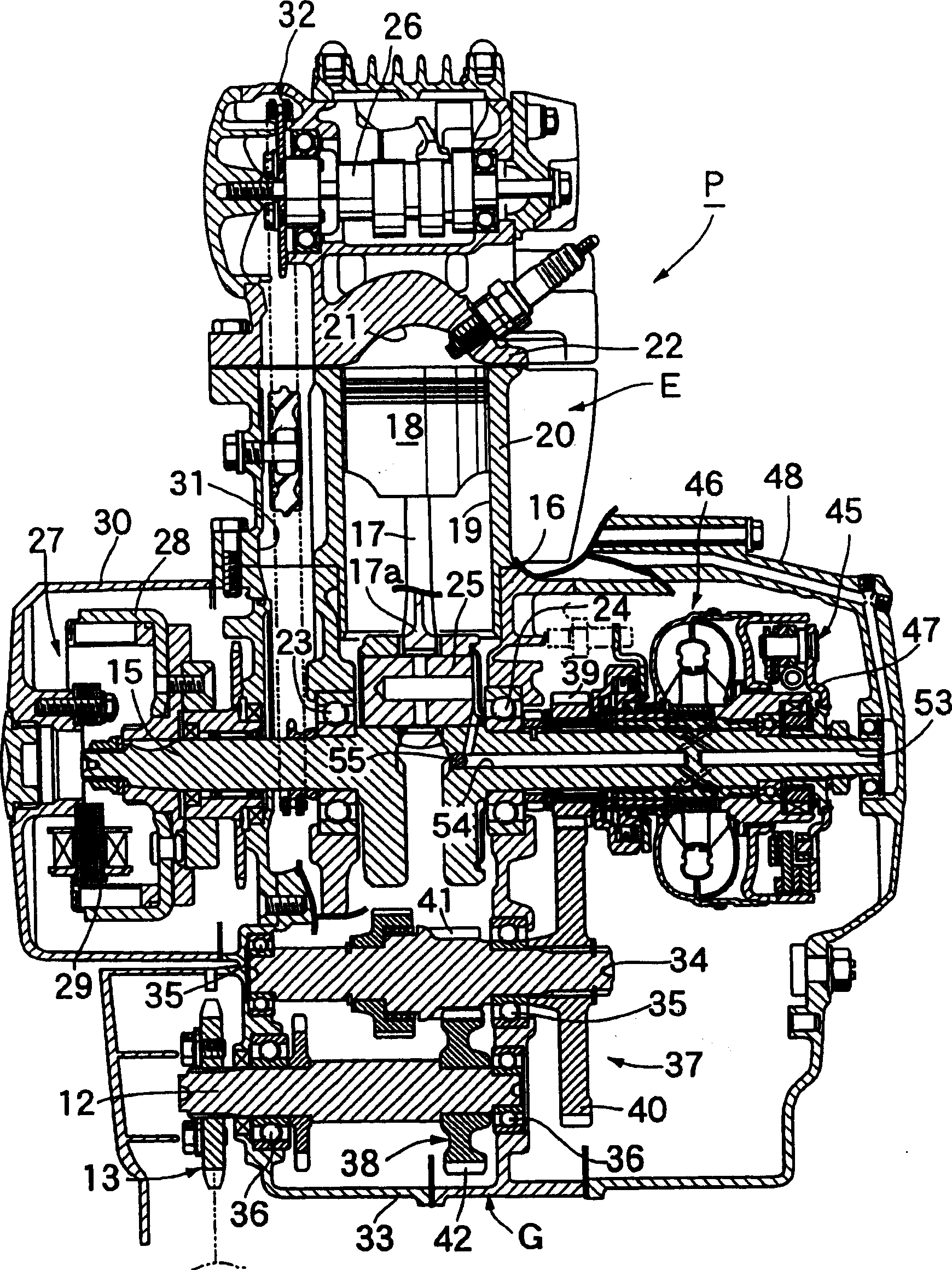
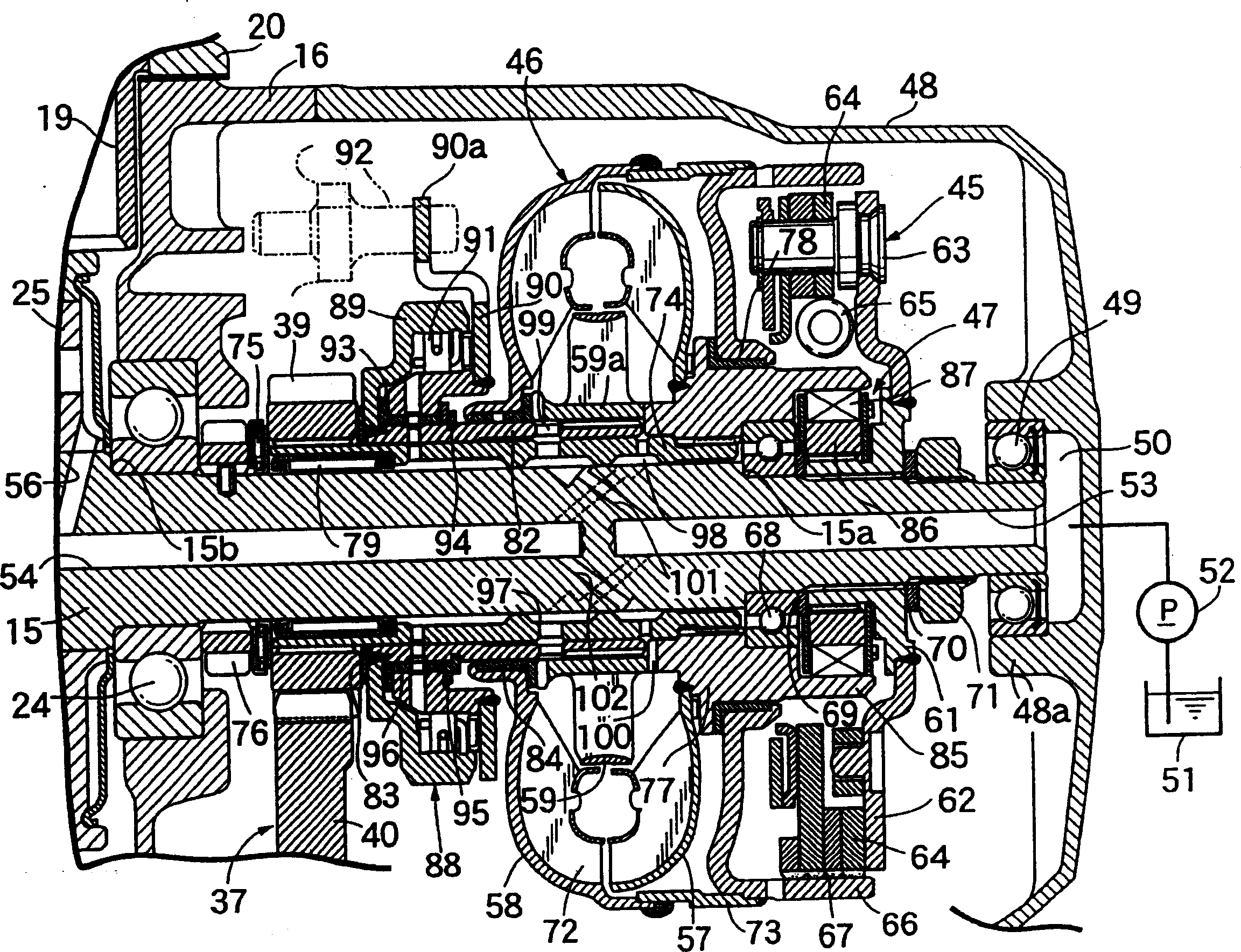
[0017] Figure 1 ~ Figure 3 represents an embodiment of the present invention, figure 1 is a side view of a motorcycle, figure 2 is a longitudinal sectional view of the power unit, image 3 yes figure 2 Sectional view of the main part.

[0018] first, figure 1 Among them, the front fork 6 is supported in a turnable manner on the head pipe 5 equipped at the front end of the frame F of the motorcycle, and the front fork 6 pivotally supports the front wheel W. The pivot plate 7 supports the swing arm 8 so as to be able to swing up and down, the rear end of the swing arm 8 pivotally supports the rear wheel WR, and the fuel tank 10 and The seat 11 covers the fuel tank 10 .

[0019] The power unit P composed of the engine E and the reducer G is assembled on the frame F, and is arranged between the pivot plate 7 and the front wheel WF...


PUM


Abstract

The present invention refers to a transmission device comprising an oil passage for supplying oil to a stalling torque converter, where a turbine rotor, a pump rotor, and a stator rotor are supported on a rotating axis and on a passage for discharging oil, said passage leading the oil discharged from the converter. The turbine, pump and stator rotors are axially arranged with regard to the rotary axis and spaced therebetween. The flow resistance can be avoided by ensuring a continuous oil flow at the front and rear portion of the converter, thereby improving the efficiency of the converter transmission and increasing the freedom degree in the arrangement. The invention comprises a stalling torque converter 46 attached to the rotary axis 15, where a turbine rotor 57 is placed adjacent the oil supply passage 53; a pump rotor 58 is placed adjacent an oil discharge passage 54; a tilted oil passage is placed adjacent the oil supply passage 101 for leading oil from the oil supply passage 53 to the pump rotor 58, and finally a tilted oil passage is placed adjacent the oil discharge passage 102 for leading the oil discharged from the turbine rotor 57.

Description

technical field [0001] The present invention relates to a supply oil passage for supplying hydraulic oil to a torque converter supporting a worm wheel, a pump impeller, and a stator impeller on a rotating shaft, and a discharge oil passage for leading out hydraulic oil discharged from the torque converter extending along the axial direction of the rotating shaft. , and the improvement of the transmission device arranged on the rotating shaft spaced apart from each other. Background technique [0002] There is known a transmission device for a small vehicle, such as described in Patent Document 1, in which a torque converter is provided between the crankshaft of the engine and the transmission, and a worm wheel, a pump impeller, and a stator impeller are arranged on the crankshaft. On the crankshaft, a supply oil passage for supplying hydraulic oil to the torque converter and a discharge oil passage for leading hydraulic oil discharged from the torque converter are coaxially ...

Claims


Application Information

Patent Timeline
IPC IPC(8): F16H41/00F16H41/04F16H41/30F16H45/00
CPCF16H2045/002B60K17/06
Inventor 山下胜山本敏弘熊谷吉彦椿野幸博
Owner HONDA MOTOR CO LTD
Why Eureka
Try Eureka