
Radio communication system

A wireless communication system and wireless communication technology, applied in the field of wireless communication systems, can solve the problem that the fourth terminal station cannot receive beacons, etc., and achieve the effect of improving the overall data transmission efficiency and preventing overlap

Inactive Publication Date: 2005-11-23
SONY GRP CORP
View PDF1 Cites 6 Cited by
  • Summary
  • Abstract
  • Description
  • Claims
  • Application Information

AI Technical Summary

Problems solved by technology

Therefore, if the beacon interval is extended, the timing of intermittent reception becomes different from the timing of beacon transmission, so that the fourth terminal station operating in the intermittent reception mode cannot receive the beacon, which is a problem

Method used


Image

  • Radio communication system
  • Radio communication system
  • Radio communication system

Examples


Embodiment Construction

[0032] Hereinafter, an embodiment of the present invention will be described in detail with reference to the accompanying drawings.

[0033] (1) Overall structure of the wireless LAN system

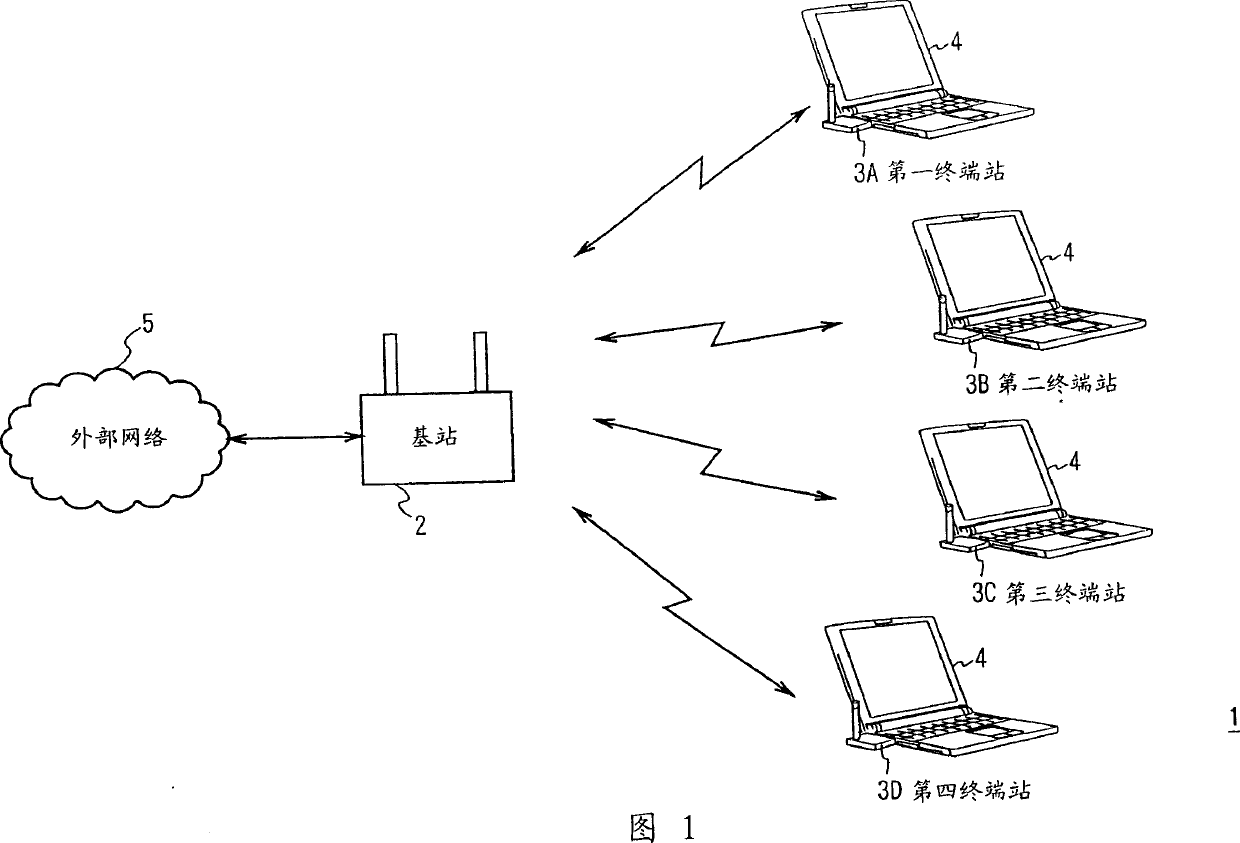
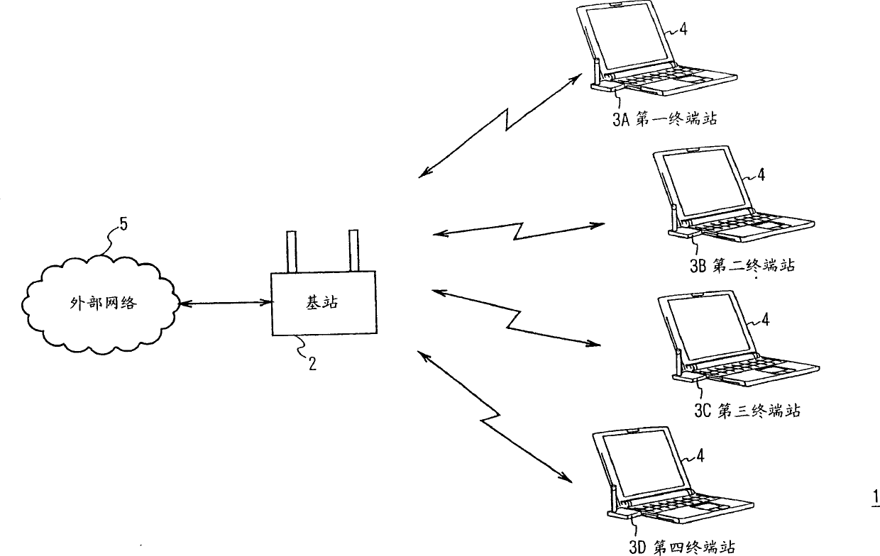
[0034] Referring to FIG. 1, reference numeral 1 generally shows a wireless LAN system as a wireless communication system according to the present invention, and this system consists of a base station 2 as a wireless communication management device and first to fourth terminal stations 3 (3A to 3D) Composition. The base station 2 and the terminal stations 3A to 3D perform wireless communication with each other using, for example, the CSMA / CA scheme in the 5 GHz band.

[0035] Actually, the terminal stations 3A to 3D as wireless terminal devices are PC card type wireless LAN cards and are inserted into PC card slots of corresponding notebook personal computers (hereinafter referred to as notebook personal computers) 4 . On the other hand, the base station 2 is connected to an external net...


PUM


Abstract

To realize a wireless communication system capable of keeping a beacon interval fixed, keeping transmission quality, and performing intermittence reception without fail. A wireless communication management device includes and transmits beacon time period information in a main beacon and a sub beacon. Then, a wireless terminal device divides transmission data based on the beacon time period information so that the transmission of the transmission data is finished before the transmission of a main beacon is started. Thereby, overlap of transmission timings of the beacon and the transmission data can be prevented and the beacon interval can be made fixed. This can keep transmission quality, makes the wireless terminal device to perform intermittence reception without fail, and improve the entire data transmission efficiency of the system.

Description

technical field [0001] The present invention relates to a wireless communication system, and is particularly suitable for application to, for example, a wireless LAN (Local Area Network) system. Background technique [0002] In recent years, wireless LAN systems are widely used, among which IEEE (Institute of Electrical and Electronics Engineers) 802.11b and IEEE802.11a are typical systems. In an IEEE802.11 type wireless LAN system, an autonomous decentralized system is used (for example, refer to Patent Reference 1), which uses a CSMS / CA (Carrier Sense Multiple Access / Collision Avoidance) scheme as an access scheme. [0003] That is, FIG. 9 shows a protocol stack of the lower two layers in the OSI (Open System Interconnection) model of a wireless LAN system of the IEEE802.11 type, which is composed of a data link layer 901 and a physical layer 902 . [0004] The data link layer 901 is divided into an LLC (Logical Link Control) sublayer 903 and a MAC (Media Access Control) ...

Claims


Application Information

Patent Timeline
Patent Type & Authority Applications(China)
IPC IPC(8): H04J11/00H04L12/28
CPCH04W48/12H04W56/00H04W84/12
Inventor 福田邦夫
Owner SONY GRP CORP
Learn More