


Quick Research
Generate reliable direction feasibility study reports for your R&D in just a few steps.

Technical Q&A
Discover and master advanced knowledge NOW. Basics, ideas, possibilities, all at once.

Find Solutions
As an expert in R&D theories, this can generate solutions to your technical problems instantly.

Evaluate Feasibility
Analyze your overall solution with one click, know your potential R&D risks in advance.

Monitor Landscape
Get weekly tech updates, stay abreast of the latest tech innovations and key insights.
Distributed Raman amplifier
A Raman amplifier, distributed technology, applied in instruments, optics, electrical components, etc., can solve problems such as complex implementation means
- Summary
- Abstract
- Description
- Claims
- Application Information
AI Technical Summary
Problems solved by technology
Method used
Image

Examples
Embodiment Construction
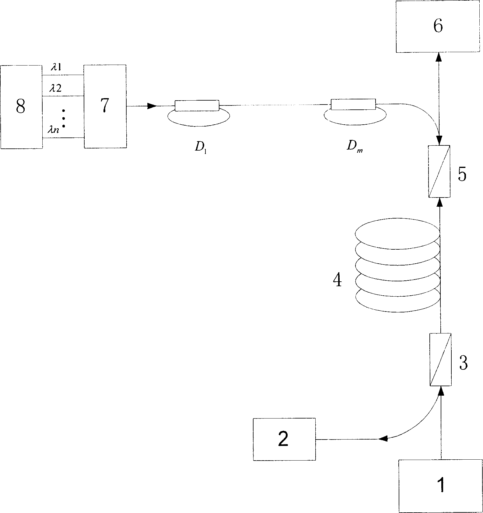
[0026] Such as image 3 As shown, the present invention includes a pump light laser 8 , a signal light laser 1 , a transmission fiber 4 , a multiplexer 5 and a demultiplexer 3 . Both ends of the signal fiber 4 are respectively connected with a multiplexer 5 and a multiplexer 3 , and the signal light emitted by the signal light laser 1 is output to the receiver 6 through the signal fiber 4 . The pump laser 8 is connected to the multiplexer 5 through 2×2 directional couplers D1, Dm, etc. The coupler is also provided with a loop fiber, that is, connecting one output end of the directional coupler with an input end with an optical fiber to form a fiber delay loop, that is, D in the figure 1 、D m and other structures. Due to the effect of the delay ring, the pump light output from the pump light laser 8 to the multiplexer 5 will become a superposition of a series of mutually uncorrelated lights, thereby achieving the purpose of eliminating polarization. The pumping light enters...
PUM
 Abstract
Description
Claims
Application Information
 - R&D Engineer
- R&D Manager
- IP Professional
- Industry Leading Data Capabilities
- Powerful AI technology
- Patent DNA Extraction
Browse by: Latest US Patents, China's latest patents, Technical Efficacy Thesaurus, Application Domain, Technology Topic, Popular Technical Reports.
© 2024 PatSnap. All rights reserved.Legal|Privacy policy|Modern Slavery Act Transparency Statement|Sitemap|About US| Contact US: help@patsnap.com