


Quick Research
Generate reliable direction feasibility study reports for your R&D in just a few steps.

Technical Q&A
Discover and master advanced knowledge NOW. Basics, ideas, possibilities, all at once.

Find Solutions
As an expert in R&D theories, this can generate solutions to your technical problems instantly.

Evaluate Feasibility
Analyze your overall solution with one click, know your potential R&D risks in advance.

Monitor Landscape
Get weekly tech updates, stay abreast of the latest tech innovations and key insights.
Depolarizer based on meta-material
A depolarizer and metamaterial technology, applied in the field of metamaterials, can solve problems such as technical complexity, and achieve the effect of easy implementation and simple structure
- Summary
- Abstract
- Description
- Claims
- Application Information
AI Technical Summary
Problems solved by technology
Method used
Image

Examples
no. 1 example
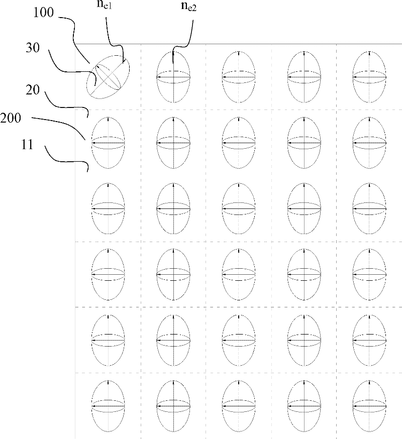
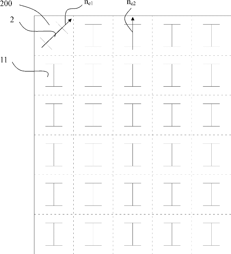
[0030] Such as figure 1 As shown, in this example, there is only one cell whose optical axis n e1 Unlike other places, n e2 Indicates the optical axis of other cells, as can be seen from the figure, n e1 with n e2 Not parallel. figure 2 Shown is an artificial microstructure using an I-shaped structure to achieve figure 1 Optical axis plane distribution shown. In this embodiment, after the electromagnetic wave with a single polarization characteristic passes through all the cells, the optical axis is n e1 Part of the cell's electromagnetic wave polarization properties will be different from others. figure 1 It is only a schematic plan view of one sheet in this embodiment, and other sheets can be combined with figure 1 The sheets shown have the same distribution of optical axes, or they may be different, as long as the polarization characteristic of the emitted electromagnetic wave is changed. Figure 8 A schematic of the stacking of the sheets is shown.
no. 2 example
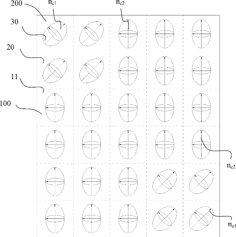
[0032] Such as image 3 As shown, in this example, the optical axis n e1 The rotated parts are at the upper left and lower right corners of the metamaterial, n e2 Indicates other optical axes, n e1 with n e2 Not parallel. Figure 4 Shown is an artificial microstructure using an I-shaped structure to achieve image 3 Optical axis plane distribution shown. In this embodiment, after the electromagnetic wave with a single polarization characteristic passes through all the cells, the optical axis is n e1 Part of the cell's electromagnetic wave polarization properties will be different from others. Similarly, image 3 It is only a schematic plan view of one sheet in this embodiment, and other sheets can be combined with image 3 The sheets shown have the same distribution of optical axes, or they may be different, as long as the polarization characteristic of the emitted electromagnetic wave is changed. Figure 8 A schematic of the stacking of the sheets is shown.
no. 3 example
[0034] Such as Figure 5 As shown, in this embodiment, such as image 3 As shown, in this embodiment, the optical axes of the refractive index ellipsoids of all the unit cells on the same layer are not parallel. Figure 6 Shown is an artificial microstructure using an I-shaped structure to achieve Figure 5 Optical axis plane distribution shown. When the incident electromagnetic wave passes through the first sheet, in different cells, its electric field can be decomposed into two mutually perpendicular electric field components in the refractive index ellipsoid of the cell (one parallel to the optical axis, one parallel to the optical axis vertical). By designing the depolarizer of the present invention so that each unit cell is anisotropic, and ensuring that the optical axis orientations of the refractive index ellipsoids of the unit cells at different positions are not the same, the polarized wave electric field of a single characteristic After the vector decomposition, ...
PUM
 Abstract
Description
Claims
Application Information
 - R&D Engineer
- R&D Manager
- IP Professional
- Industry Leading Data Capabilities
- Powerful AI technology
- Patent DNA Extraction
Browse by: Latest US Patents, China's latest patents, Technical Efficacy Thesaurus, Application Domain, Technology Topic, Popular Technical Reports.
© 2024 PatSnap. All rights reserved.Legal|Privacy policy|Modern Slavery Act Transparency Statement|Sitemap|About US| Contact US: help@patsnap.com