
Brushless DC electric machine in structure of short magnetic circuit

A brushed DC motor, short magnetic circuit technology, applied in the magnetic circuit shape/style/structure, motor, magnetic circuit static parts and other directions, can solve the problems of limiting motor efficiency, large stator iron loss, affecting current control accuracy, etc.

Inactive Publication Date: 2005-11-16
HARBIN INST OF TECH
View PDF0 Cites 9 Cited by
  • Summary
  • Abstract
  • Description
  • Claims
  • Application Information

AI Technical Summary

Problems solved by technology

[0002] The armature of the brushless DC motor in the prior art mostly adopts the distributed winding structure and the concentrated winding structure. When using these two winding structures, there is magnetic coupling between the phases in the armature. There is a control accuracy that affects the current; on the other hand, because the magnetic flux generated by each phase winding passes through a long magnetic circuit, the stator iron loss is relatively large, which limits the further improvement of the motor efficiency

Method used


Image

  • Brushless DC electric machine in structure of short magnetic circuit
  • Brushless DC electric machine in structure of short magnetic circuit
  • Brushless DC electric machine in structure of short magnetic circuit

Examples


specific Embodiment approach 1

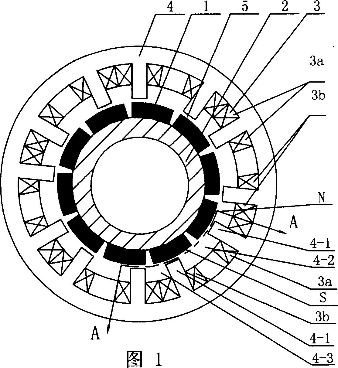
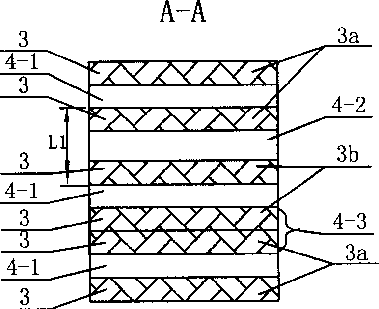
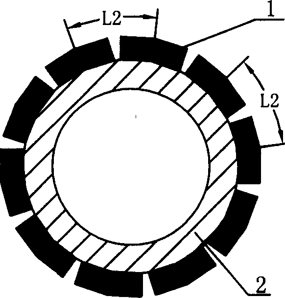
[0005] Specific implementation mode one: in conjunction with Fig. 1, figure 2 and image 3 Describe this specific embodiment, this specific embodiment is made up of stator 4, a plurality of permanent magnets 1, rotor 2, excitation winding 3; Stator 4 is a cylindrical sleeve, rotor 2 is a cylindrical tube; And take the rotation axis of the rotor 2 as the central axis to be evenly spaced from each other, the length direction of each permanent magnet 1 is parallel to the axis of the rotor 2 and the length of the permanent magnet 1 runs through the outer surface of the cylinder of the rotor 2; the stator 4 are set on the outside of the rotor 2, and an air gap 5 is left between the inner surface of the cylindrical sleeve of the stator 4 and the outer surface of the permanent magnet 1, and the axis line of the stator 4 coincides with the rotation axis of the rotor 2; the stator 4 There are a plurality of wide grooves 4-2 and narrow grooves 4-3 on the inner surface of the cylindrica...

specific Embodiment approach 2

[0006] Specific implementation mode two: combination Figure 4 and Figure 5 Describe this specific embodiment. The difference between this specific embodiment and specific embodiment 1 is that there are a plurality of deep grooves 2-1 uniformly opened on the outer cylindrical surface of the rotor 2, and each deep groove 2-1 is embedded with a The permanent magnet 1 adopts tangential magnetization, and the N pole and the S pole of the permanent magnet 1 are respectively connected to the two vertical walls of the deep groove 2-1; the center distance between every two adjacent deep grooves 2-1 The length of L3 is equal to the width L1 of the wide slot 4-2 on the stator 4.


PUM


Abstract

Improving structure of magnetic path for brushless type DC electric machine, the invention eliminates magnetic coupling between phases in armature. The machine includes stator, multiple permanent magnets, rotor, and excitation winding. There are multiple wide slots and narrow slots opened on inner surface of column sheath of stator. Thickness of pole body between wide slot and narrow slot is same. The excitation winding is wound on root part of pole body. Located at two sides of wide slot, first excitation winding and second excitation winding are connected in series. Sheathed on the rotor, stator and rotor are coaxial, and there is air gap between them. The invention shortens magnetic path of excitation magnetic flux of winding so as to raise efficiency of machine and control precision. Said machine can be used as electromotor or generator, applicable to robot, number control machine tool and electric vehicles.

Description

Technical field: [0001] The invention relates to a brushless direct current motor, in particular to an improvement of a magnetic circuit structure of the brushless direct current motor. Background technique: [0002] The armature of the brushless DC motor in the prior art mostly adopts the distributed winding structure and the concentrated winding structure. When using these two winding structures, there is magnetic coupling between the phases in the armature. It affects the control accuracy of the current; on the other hand, the stator iron loss is relatively large because the magnetic flux generated by the energization of each phase winding passes through a long magnetic circuit, which limits the further improvement of the motor efficiency. Invention content: [0003] The object of the present invention is to design a brushless DC motor with a short magnetic circuit structure in order to solve the problems that the magnetic coupling between the phases in the armature aff...

Claims


Application Information

Patent Timeline
Patent Type & Authority Applications(China)
IPC IPC(8): H02K1/16
CPCY02T10/641Y02T10/64
Inventor 寇宝泉吴红星程树康李立毅
Owner HARBIN INST OF TECH
Learn More