Disk device
一种盘片、底盘的技术,应用在盘片装置领域,能够解决脱落等问题
- Summary
- Abstract
- Description
- Claims
- Application Information
AI Technical Summary
Problems solved by technology
Method used
Image

Examples
Embodiment approach 1
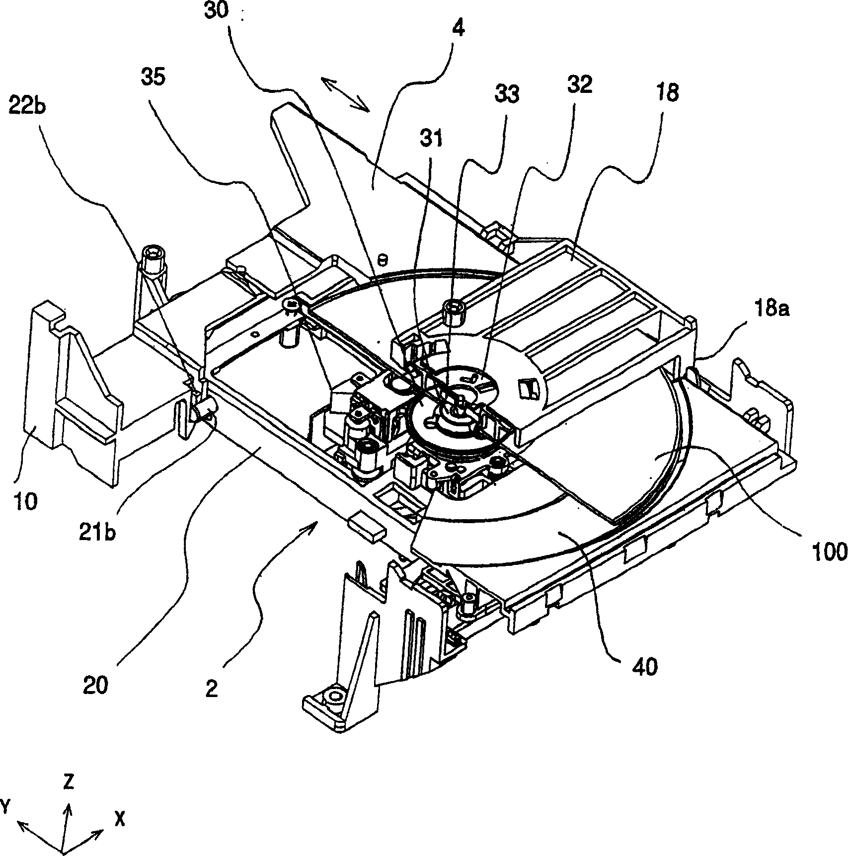
[0030] figure 1 It is a perspective view showing the disk drive of Embodiment 1. The disk device includes a main chassis 10 , a rotary chassis 20 rotatably supported by the main chassis 10 , and a tray 4 reciprocally supported by the main chassis 10 . The tray 4 has a mounting surface 40 that holds the disk medium 100 horizontally, and is horizontally conveyed between a storage position inside the disk device and a discharge position outside the disk device.
[0031] The following instructions are as figure 1 As shown, the direction perpendicular to the mounting surface 40 of the tray 4 is defined as the Z-axis, and the moving direction of the tray 4 is defined as the Y-axis. In addition, let the direction perpendicular to the Y axis and the Z axis be the X axis. Here, regarding the Z-axis, the direction from the tray 4 toward the disk medium 100 is defined as a positive side, and the opposite direction is defined as a negative side. In the Y-axis, the direction in which...
Embodiment approach 2
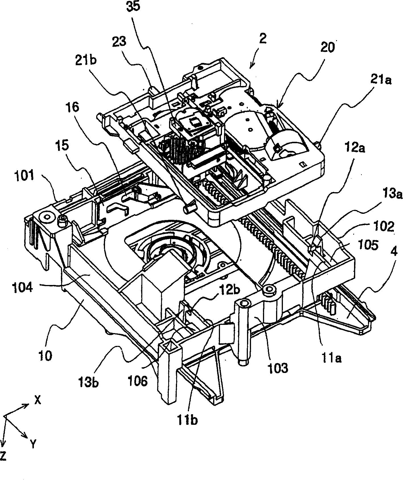
[0049] Figure 10 and Figure 11 It is a perspective view showing the negative side in the Z-axis direction as the upper side and the positive side in the Y-axis direction as the lower left side. Figure 10 Indicates the state in which the rotating assembly 2 is about to be assembled to the disk drive of Embodiment 2, Figure 11 It shows the state after the rotary unit 2 is assembled to the disk drive.
[0050] Such as Figure 10 and Figure 11 As shown, in the main chassis 10 , protrusion support portions 5 a , 5 b for supporting the protrusions 21 a , 21 b of the rotating chassis 20 are respectively formed on the outer side of the rotating chassis 20 in the X-axis direction. The protrusion support parts 5 a and 5 b each have side walls 6 a and 6 b extending in the Y-axis direction from the outer peripheral wall 103 of the main chassis 10 . The side walls 6a, 6b each have a horizontal end face (end face parallel to the XY plane) facing the negative side of the Z-axis dir...
Embodiment approach 3
[0060] Figure 13 and Figure 14 It is a perspective view showing the negative side in the Z-axis direction as the upper side and the positive side in the Y-axis direction as the lower left side. Figure 13 Shown is the state of the disk drive in Embodiment 3 just before the rotation unit 2 is assembled, Figure 14 Shown is a state in which the rotary assembly 2 is assembled to the disk drive. In the disk drive according to the third embodiment, the protrusion support portions 5a, 5b of the main chassis 10 are configured in the same manner as in the second embodiment. That is, the insertion direction of the protrusions 21a, 21b into the protrusion supports 5a, 5b is the Y-axis direction, whereby the structures of the protrusions 21a, 21b are not easily detached from the protrusion supports 5a, 5b. In addition, in this Embodiment 3, the same protrusion 22a, 22b as Embodiment 1 is formed in the front-end|tip part of the protrusion part 21a, 21b of the rotating chassis 20. As ...
PUM
 Abstract
Description
Claims
Application Information
 - R&D
- Intellectual Property
- Life Sciences
- Materials
- Tech Scout
- Unparalleled Data Quality
- Higher Quality Content
- 60% Fewer Hallucinations
Browse by: Latest US Patents, China's latest patents, Technical Efficacy Thesaurus, Application Domain, Technology Topic, Popular Technical Reports.
© 2025 PatSnap. All rights reserved.Legal|Privacy policy|Modern Slavery Act Transparency Statement|Sitemap|About US| Contact US: help@patsnap.com