Non-reversible circuit element and method of manufacture

A technology for circuit components and manufacturing methods, which is applied in the direction of electrical components, circuits, waveguide devices, etc., can solve the problems of poor processability, thickening of the ground terminal 55, poor grounding performance of the second yoke 54, etc., to improve processability, The effect of firm installation

Inactive Publication Date: 2005-11-02
ALPS ALPINE CO LTD
View PDF0 Cites 0 Cited by
  • Summary
  • Abstract
  • Description
  • Claims
  • Application Information

AI Technical Summary

Problems solved by technology

[0014] However, in the conventional non-reciprocal circuit element, since the ground terminal 55 and the input / output terminal 56 are formed in a substantially U-shape, the connection portions 55a, 56a are located on the bottom wall 53b of the resin case 53, and formed on the bottom wall 53b from the second yoke 54. Since the bottom plate 54a is separated upward, the thickness of the bottom wall 53b of the resin case 53 becomes thicker, making it impossible to reduce the thickness.
[0015] In addition, since the ground terminal 55 is cut from the second yoke 54, not only the grounding performance of the second yoke 54 is poor, but also the workability of the ground terminal 55 is poor.
[0016] In addition, in the conventional manufacturing method of the nonreciprocal circuit element, since the ground terminal 55 is cut off from the second yoke 54 to manufacture, not only the workability of the ground terminal 55 is poor, but also the connecting portion between the ground terminal 55 and the input / output terminal 56 55a, 56a are located on the bottom wall 53b of the resin case 53, and are separated upward from the bottom plate 54a of the second yoke 54, so the thickness of the bottom wall 53b of the resin case 53 is thickened, and thinning cannot be achieved.
[0017] However, in the conventional non-reciprocal circuit element, since the ground terminal 55 and the input / output terminal 56 are substantially U-shaped, the connection portions 55a, 56a are located on the bottom wall 53b of the resin housing 53, and formed from the bottom plate of the second yoke 54. 54a is separated upwards, so the thickness of the bottom wall 53b of the resin case 53 is thickened, and it cannot be thinned.
[0018] In addition, since the ground terminal 55 is cut off from the second yoke 54, there is a problem that not only the grounding performance of the second yoke 54 is poor, but also the processability of the ground terminal 55 is poor.
[0019] In addition, in the conventional manufacturing method of the nonreciprocal circuit element, since the ground terminal 55 is cut off from the second yoke 54 to manufacture, not only the workability of the ground terminal 55 is poor, but also the connecting portion between the ground terminal 55 and the input / output terminal 56 55a, 56a are located on the bottom wall 53b of the resin case 53, and since they are separated upward from the bottom plate 54a of the second yoke 54, the thickness of the bottom wall 53b of the resin case 53 is thickened, and there is no The problem of thinning

Method used


Image

  • Non-reversible circuit element and method of manufacture
  • Non-reversible circuit element and method of manufacture
  • Non-reversible circuit element and method of manufacture

Examples


Embodiment Construction

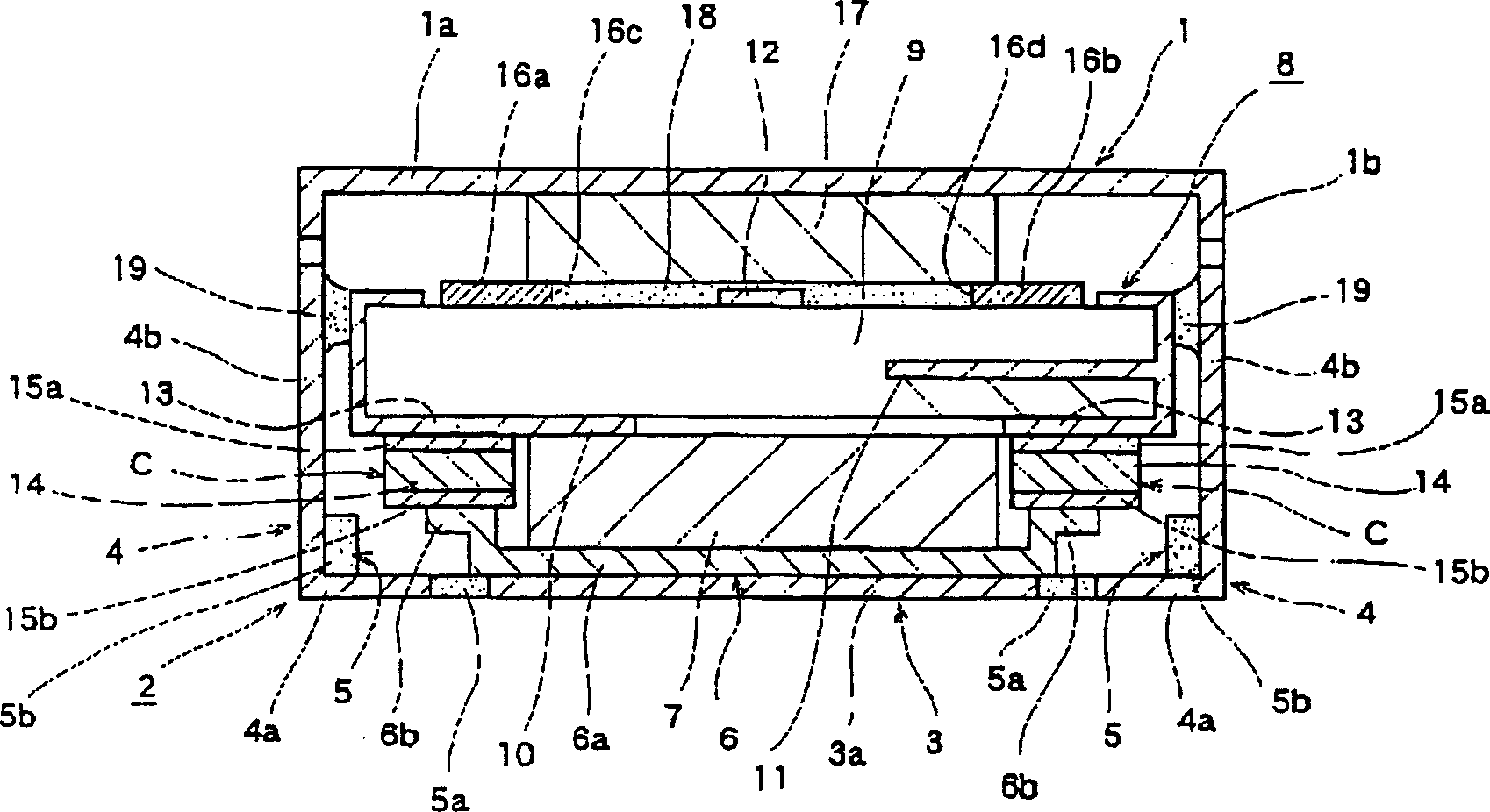
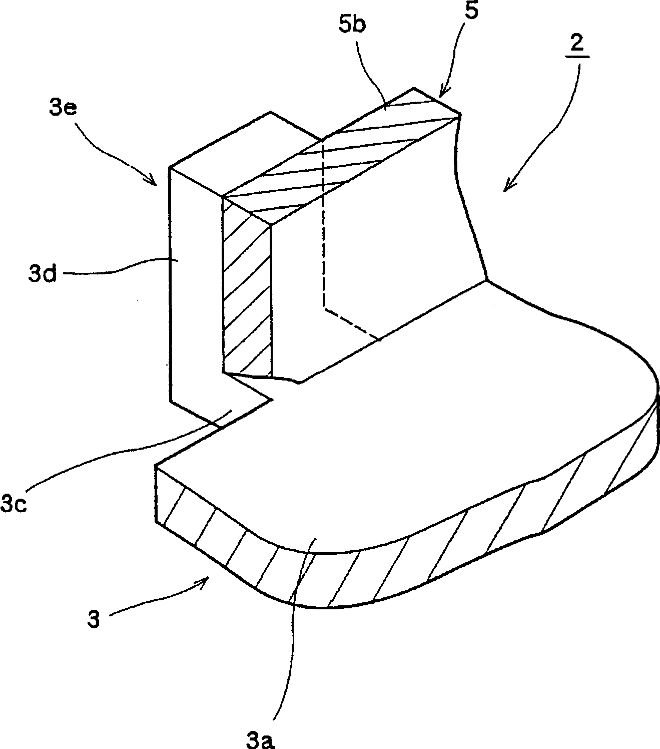
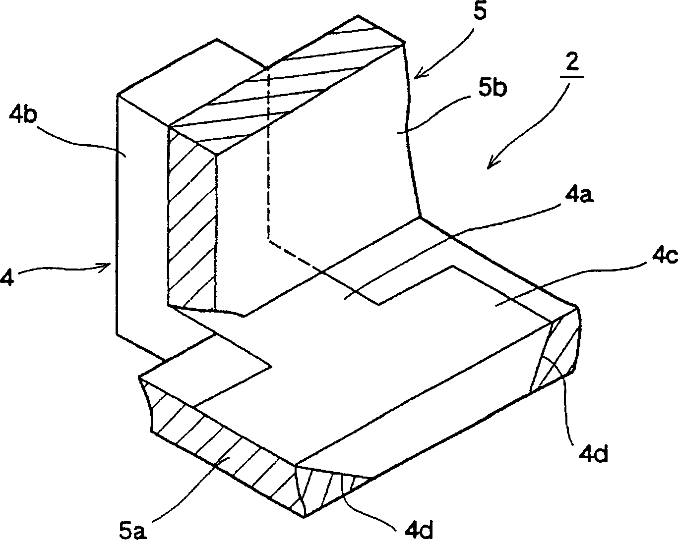
[0053] First explain the non-reciprocal circuit element of the present invention and its manufacturing method, figure 1 It is a sectional view of main parts of the non-reciprocal circuit element of the present invention, figure 2 It is an enlarged sectional view of main parts of the ground terminal of the non-reciprocal circuit element of the present invention, image 3 It is an enlarged sectional view of main parts of the input and output terminals of the non-reciprocal circuit element of the present invention, Figure 4 is a top view of the module body of the non-reciprocal circuit element of the present invention, Figure 5 It is an exploded perspective view of a magnet and a module body of a non-reciprocal circuit element of the present invention, Figure 6 It is an explanatory diagram showing the first step of the manufacturing method of the nonreciprocal circuit element of the present invention, Figure 7 It is an explanatory drawing which shows the 2nd process of t...


PUM


Abstract

In this non-reciprocal circuit element, a box-like member 2 for accommodating a ferrite member 7 is formed of a second yoke 3 and an insulating resin body 5. A ground terminal 3e embedded in the resin body 5 has a coupling section 3c coupled to a bottom plate 3a and a bent tongue piece 3d extending along the external wall of the side wall 5b of the resin body 5. An L-shaped input / output terminal 4 embedded in the resin body 5 has a bottom 4a in the same plane state as the bottom plate 3a, and a bent side 4b extending along the external surface of the side wall 5b of the resin body 5. Thus, the bottom piece 4a of the input / output terminal 4 is in the same surface state as the bottom plate 3a of the second yoke 3, the thickness of the bottom wall of the box-like member 2 can be reduced, and a thin element can be obtained.

Description

technical field [0001] The present invention relates to a non-reciprocal circuit element composed of an isolator or a circulator used in a transmission unit of a mobile communication device such as a mobile phone, and a method for manufacturing the same. Background technique [0002] Firstly, drawings explaining a conventional non-reciprocal circuit element and its manufacturing method, Figure 8 It is an exploded perspective view of a conventional non-reciprocal circuit element, Figure 9 It is a cross-sectional view of main parts of a resin case of a conventional non-reciprocal circuit element, Figure 10 It is an explanatory diagram showing the first step of a conventional method of manufacturing a nonreciprocal circuit element, Figure 11 It is an explanatory diagram showing the second step of a conventional method of manufacturing a nonreciprocal circuit element, Figure 12 It is an explanatory diagram showing the third step of the conventional manufacturing method of...

Claims


Application Information

Patent Timeline
IPC IPC(8): H01P1/36H01P1/383
Inventor 高野敦雄境晃
Owner ALPS ALPINE CO LTD
Why Eureka
Try Eureka