
System for observing wave in waterway

An observation system and wave technology, applied in the new channel wave observation system field, can solve the problems of difficult management, reduced accuracy in high frequency bands, and inability to move up and down, and achieve the effects of high safety, easy management, and safety of the observation system

Inactive Publication Date: 2005-10-26
SOUTH CHINA SEA INST OF OCEANOLOGY - CHINESE ACAD OF SCI
View PDF0 Cites 12 Cited by
  • Summary
  • Abstract
  • Description
  • Claims
  • Application Information

AI Technical Summary

Problems solved by technology

For example, accelerometers (usually wave measuring buoys) are required to follow the waves very well. Since they are placed on the sea surface, their management is difficult and they are easily damaged by man, especially on the channel, which will affect the normal navigation of ships. Also vulnerable to being hit by ships
Since the pressure type wave measuring instrument is placed underwater, the safety is better. During the measurement, the instrument is required to be fixed at a certain position and cannot be moved up and down, so that the change of water pressure above the instrument can be accurately sensed, and the wave height, wave height and period; because of the filtering effect of the water layer, the high-frequency band of the pressure data is attenuated, and the attenuation is a strong function of the wave period. As the depth increases, the accuracy of the high-frequency band of the wave spectrum decreases. Within 15m, the measurement effect is better, and the closer to the sea surface, the better the effect, but the closer to the sea surface, its safety and the impact on ship navigation have also become issues that must be considered

Method used


Image

  • System for observing wave in waterway
  • System for observing wave in waterway

Examples


Embodiment Construction

[0011] The following is attached figure 1 And figure 2 The circuit example of to further illustrate the implementation of the present invention:

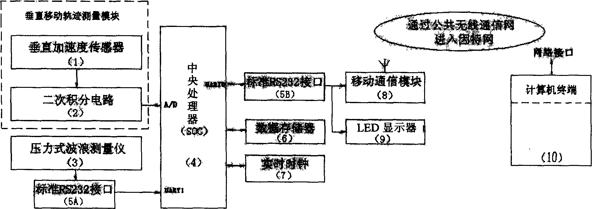
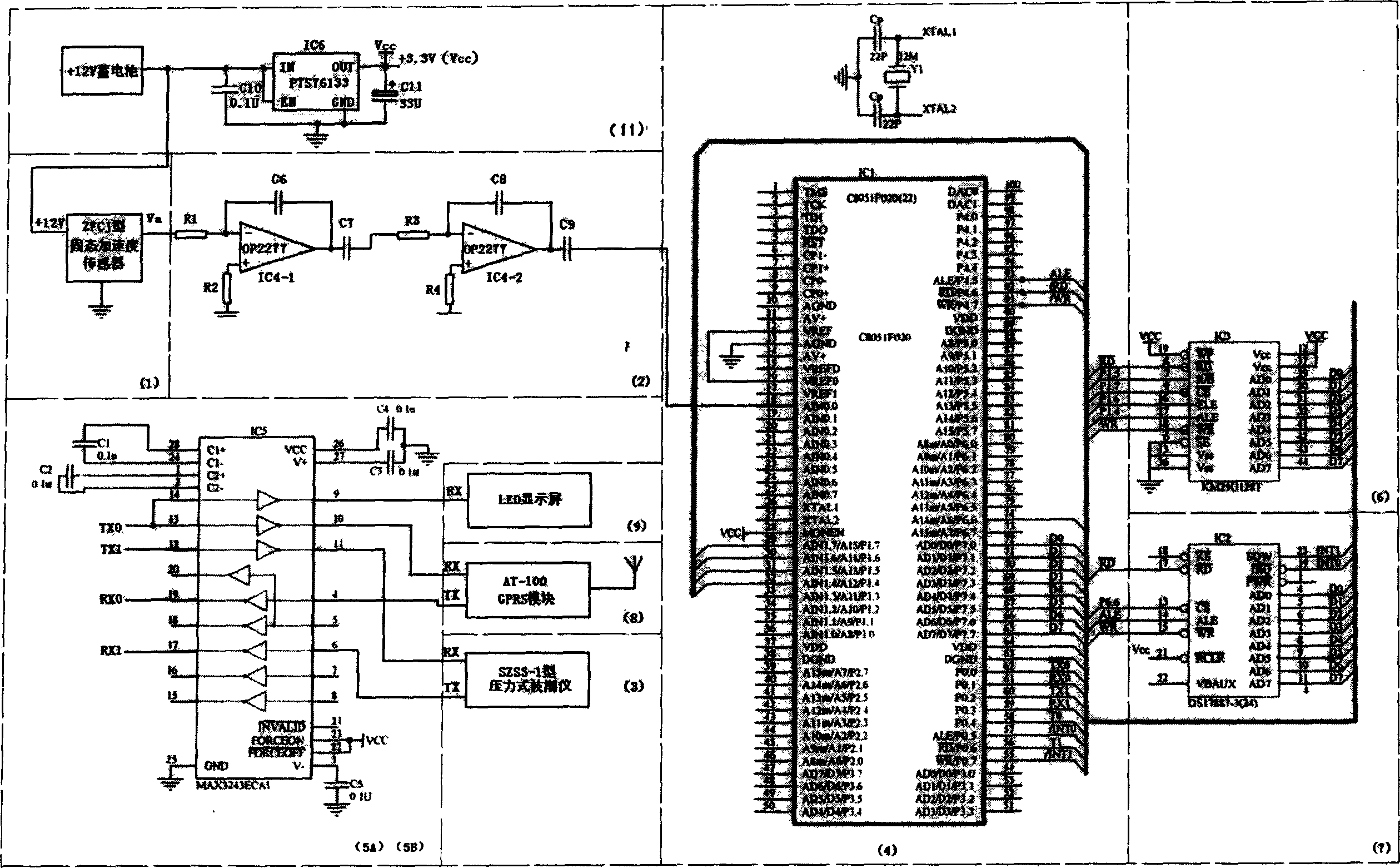
[0012] As attached figure 1 As shown, this embodiment establishes a system that includes a vertical acceleration sensor (1), a quadratic integration circuit (2), a pressure wave measuring instrument (3), a central processing unit (4), and a standard RS232 interface (5A, 5B) , Data storage (6), real-time clock (7), mobile communication module (8), on-site display (LED) (9), computer terminal (10) composed of a system. Circuit example is attached figure 2 As shown, the vertical acceleration sensor (1) can be a ZFCJ solid-state acceleration sensor, and its output signal is sent to the second integration circuit (2). R1, C6 and IC4-1 form a primary integration circuit, and R3, C8 and IC4-2 form the first integration circuit. Quadratic integration circuit, C7 and C9 are DC blocking capacitors. The acceleration signal is integrated by the q...


PUM


Abstract

The invention provides a fairway wave observation system, which comprises the vertical movable track measuring module composed of the vertical speeding sensor and twice integral circuit, the pressure wave measurer, the central processor, the standard RS232 interface, the data memorizer, the real-time clock, the mobile communication module, the LED displayer and the computer terminal. The central processor and the vertical movable track measuring module are equipped on the floating carrier. The pressure wave measurer is hung up the underwater of the said floating carrier. The speeding sensor measures the acceleration of the vertical movement of the floating carrier; obtain the vertical moving track of the light boat through the twice integral circuit; the pressure wave measurer measures the wave surface track opposite to the floating carrier; the central controller composes the vertical moving track and the wave surface track to get the wave height and the period.

Description

Technical field [0001] The invention relates to a new channel wave observation system. Background technique [0002] Although wave observation has been noticed for a long time, the observation instruments and methods are not perfect. In recent decades, due to the rapid development of ocean development and utilization, the demand for wave observation data by sea-related departments has been increasing, which has greatly promoted the research work of wave observation methods. Currently commonly used wave measuring methods are: visual inspection, optical wave measuring instrument, acceleration wave measuring instrument, pressure wave measuring instrument, acoustic wave measuring instrument, airborne laser wave measuring, satellite remote sensing wave measuring, etc., each method has Its advantages and disadvantages. For example, the accelerometer (usually refers to the wave measuring buoy) requires good wave-following performance. Because it is placed on the sea surface, it is diffi...

Claims


Application Information

Patent Timeline
Patent Type & Authority Applications(China)
IPC IPC(8): G01C13/00
Inventor 龙小敏王盛安蔡树群张经汉
Owner SOUTH CHINA SEA INST OF OCEANOLOGY - CHINESE ACAD OF SCI
Learn More